
Instructions


Circuit program development
akYtec GmbH · Vahrenwalder Str. 269 A · 30179 Hannover · Germany · Tel.: +49 (0) 511 16 59 672-0 · www.akytec.de
73
7 Circuit program development
It is recommended to start creating a circuit program with planning. The plan should de-
scribe all possible states of the device during operation in form of a mode diagram, a ta-
ble of I/O states, an electrical or functional diagram, etc.
After all the operation tasks are described, the program can be developed using the
standard blocks from the toolbar Insert (Table 2.6) and the specific blocks from the pro-
ject library (sect. 6). The project library presented in Library Box (sect. 2.4) contains the
functions (sect. 6.1) and the function blocks (sect. 6.2) available for the target device, as
well as the macros added to the project (sect. 6.3).
For details about using of an individual block see sect. 7.1 – 7.8, for other practices of
program development see sect. 7.9 – 7.11.
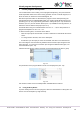
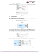
To draw connecting lines, use the left mouse button:
Click the output pin of the first block. The line is attached to it and follows the mouse
cursor.
To change the line direction, click on the workspace.
Pull the line up to the input pin of the second block and click on it to finish the line.
The connecting line can be drawn only between block connection pins assigned to the
same data type. To connect the connection pins assigned to different data types, use
conversion blocks (sect. 7.8).
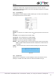
Click the block to select it. Pull the rectangle around several blocks to select a group.
Fig. 7.1
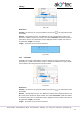
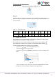
The parameters of the program blocks can be set in Property Box (sect. 2.5).
Fig. 7.2
Use element context menu for all manipulation available with the element.
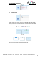
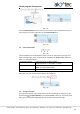
7.1 Using of library blocks
To place a library block in the circuit program, select the desired block in Library Box and
move it onto the workspace by drag-and-drop.