
Instructions


User interface
akYtec GmbH · Vahrenwalder Str. 269 A · 30179 Hannover · Germany · Tel.: +49 (0) 511 16 59 672-0 · www.akytec.de
6
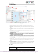
2 User interface
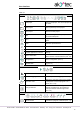
Fig. 2.1
1. Title bar – shows the name of the software and the path to the open project file
2. Menu bar – consists of the following groups: File, View, Device, Service, Plugins and
Help
3. Toolbars – Standard, Service and Insert: quick access to the essential functions of
ALP
4. Library Box – a panel that displays all the functions, function blocks, and macros
that can be added to the project
5. Property Box – a panel where the properties of the selected project element can be
viewed and modified
6. Workspace – a field in the user interface where a circuit program, display structure
or a display form can be viewed and modified
7. Status bar – shows status and error messages, target device memory usage, status
of the connected device and the programming interface
8. Display Manager – a tool to program the displayed information (available only for de-
vices with display)
9. Variable Box – a panel in which all project variables with their parameters and refer-
ences are displayed. Use drag-and-drop to place a variable block in a circuit pro-
gram.
10. Component Manager – a special tool in a separate window to access the Online Da-
tabase and to add the elements from Online Database to an offline library or to the
project library. Internet connection is needed.
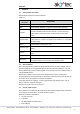
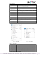
2.1 Menu
Table 2.1 Menu File
New project
Open a new project. The current project will be closed. (sect.
3.3)
Change target device
Change the target device in the project (sect. 4.8)