
Instructions


Usage basics
akYtec GmbH · Vahrenwalder Str. 269 A · 30179 Hannover · Germany · Tel.: +49 (0) 511 16 59 672-0 · www.akytec.de
19
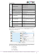
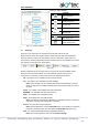
Fig. 3.2
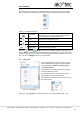
The new project appearance:
workspace empty circuit program
status bar information about available resources
Library Box available program blocks
Property Box workspace properties.
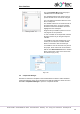
Circuit program
Now you can create the main circuit program in the workspace using the common pro-
gram blocks from the toolbar Insert and the specific program blocks from Library Box.
Draw connecting lines between inputs, outputs and program elements to establish logical
connections in the program. For details about individual program block and connecting
lines see sect. 7.
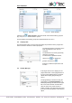
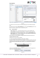
Display Manager
If the selected device has a display, the Display Manager tab appears to the left from the
workspace. With this tool you can program the displayed information.
Simulation
Program can be simulated offline. Start the simulation mode using the menu item Service
> Simulation or the toolbar icon , change the state of the inputs and notice the state of
the outputs to check the correctness of the program (sect. 7.11).
Online debugging
If the device is connected and the program in the device and in ALP is the same, you can
use online debugging to check the correctness of the program in the device (sect. 7.12).
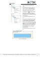
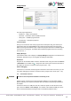
3.4 Connection to device
WARNING
The device must be powered off before connecting to PC.
Devices can be connected to PC directly (PR200, SMI200) or over PR-KP20 adapter
(PR110, PR114). The required connection cable is included in the package of PR200 or
the adapter.
Connect the device to a USB port of the PC, switch the power on and select the serial
port in the menu Device > Port settings. The number of the emulated COM port can be
found in the Windows Device Manager under “Connections (COM and LPT)”.