
Instructions
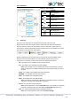


User interface
akYtec GmbH · Vahrenwalder Str. 269 A · 30179 Hannover · Germany · Tel.: +49 (0) 511 16 59 672-0 · www.akytec.de
10
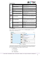
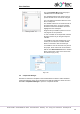
Variable output block
Variable, which value can be written in the
program (sect. 7.3)
Variable input block
Variable, which value can be read in the
program (sect. 7.3)
Constant block
Constant value (sect. 7.4)
Delay line
Feedback with one-cycle delay (sect. 7.5)
Network variable output block
Variable, which value can be written via
network (sect. 7.6)
Network variable input block
Variable, which value can be read via net-
work (sect. 7.6)
Block WriteToFB
Connects the input value of the block to the
selected parameter of the selected function
block and used to change the parameter
(sect. 7.7)
Block ReadFromFB
Connects the output value of the block to
the selected parameter of the selected
function block and used to read the param-
eter (sect. 7.7)
Conversion to BOOL
Conversion of any value to a BOOL value
(sect. 7.8)
Conversion to INT
Conversion of any value to an INT value
(sect. 7.8)
Conversion to REAL
Conversion of any value to a REAL value
(sect. 7.8)
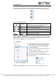
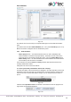
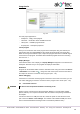
2.3 Workspace
When a project is opened, the workspace with the tab Main program is shown in the
middle part of the window (Fig. 2.7).
Fig. 2.7 Workspace
Circuit program is built and modified by placing program blocks and connecting lines be-
tween them in the workspace. The size of the workspace can be changed in Property
Box. The inputs (left) and outputs (right) are signed as follows:
Ix – digital inputs
AIx – analog inputs
Qx – relay outputs
AOx – analog outputs