
Specification

[AP1034]
016003455-E-01 - 8 - 2016/06
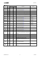
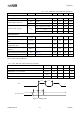
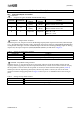
(Ta = 25°C, VM=24V, unless otherwise specified.)
Parameter
Symbol
Condition
min
typ
max
Unit
Current Operation
Blanking Time t
B
FS=”L” 1.3 2.6 5.2
µs
PWM Chopper Frequency
f
CP1
FS=”L” 20 39 60 kHz
f
CP2
FS=”H” 40 77 120 kHz
Output Current Accuracy errI
load
V
REF
=2V, %I
loadMAX
=38%
-15
-
±15
%
V
REF
=2V, %I
loadMAX
=71%
-5
-
±5
%
V
REF
=2V, %I
loadMAX
=100%
-5
-
±5
%
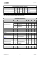
Protection Circuit
Overcurrent protection trip level I
OCPTRIP
2.5 5.0 7.5 A
Overcurrent protection deglitch
time
t
OCPDET
3.0 6.8 23.3
µs
Overcurrent protection deglitch
voltage (Low side)
VL
OCPTRIP
0.5 - 1.1 V
Under Voltage Detect Voltage
(UVLO)
VM
UVLO
5.7 6.35 7.0 V
Thermal Shut Down Temperature T
TSD
(Note 9) 150 175 200 °C
Temperature Hysteresis T
TSDHYS
(Note 9) 20 30 40 °C
Note 8. All above voltages are with respect to GND.
Note 9. Not tested in production.
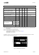
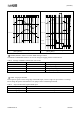
(Ta = 25°C, VM=24V, unless otherwise specified.)
Parameter Symbol min typ max Unit
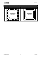
STEP Signal “H” Level Time t
WH(STEP)
1.0 - -
µs
STEP Signal “L” Level Time t
WL(STEP)
1.0 - -
µs
DIR, MODEx Signal Setup Time t
S(STEP)
200 - - ns
DIR, MODEx Signal Hold Time t
H(STEP)
200 - - ns
t
WH
(STEP)
t
WL(STEP
)
STEP
t
S(STEP)
t
H(STEP)
DIR,MODE1,MODE2
Figure 3. Timing Chart