
Specification

[AP1034]
016003455-E-01 - 7 - 2016/06
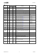
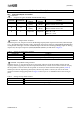
8. Recommended Operating Conditions
Parameter
Symbol
min
typ
max
Unit
Note
Motor Power Supply Voltage
VM
8.0
24.0
35.0
V
Maximum Output Current
(Continuous)
Iload - - 2.0 A (Note 6)
Reference Voltage of
PWM Constant Current Control
V
REF
0.0 - 3.6 V Iload(100%)[A]=(V
REF
/8)/RISn
Operating Temperature Range
Ta
-30
-
85
°C
Note 6. Please have a thermal design so as not exceed Tj = 150 degrees and Power Dissipation.
Note 7. All voltages are with respect defined to GND (Exposed-Pad).
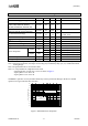
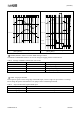
9. Electrical Characteristics
(Ta = 25°C, VM=24V, unless otherwise specified.)
Parameter
Symbol
Condition
min
typ
max
Unit
Quiescent Current
VM Quiescent Current
I
VM
ENABLEB=”L” - - 12.0 mA
I
VMOFF
ENABLEB=”L”
SLEEPB=”H”
- - 7.0 mA
I
VMPSV
SLEEPB=”L”
SLEEP MODE
- 10 30
µA
H-bridge Circuit
Driver On Resistance
R
ON
Iload = 1.5A
-
0.64 0.86
Ω
Body Diode Forward Voltage V
F
I
F
= 0.1A - 0.8 1.2 V
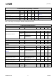
Interface
Input High Level Voltage V
IH
2.0 - - V
Input Low Level Voltage V
IL
- - 0.8 V
Input Hysteresis
(
Note 9)
Vhys
STEP, DIR, RESETB,
MODE1,MODE2,ENABLEB
0.2 0.4 V
Input Pulse Rise Time t
R
- - 1.0
µs
Input Pulse Fall Time t
F
- - 1.0
µs
Input High Level Current I
IH
STEP,DIR, ENABLEB
5.5V applying
- - 1.0
µA
Input Low Level Current I
IL
0V applying -1.0 - -
µA
Reference Voltage
VREF Input Voltage Range V
REF
0 - 3.6 V
VREF Input Current I
VREF
V
REF
=2V -3 - 3
µA