
Specification

[AP1034]
016003455-E-01 - 19 - 2016/06
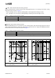
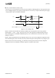
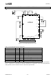
11. Recommended External Circuit
Recommended External Circuit
VDC
CVDC
VREF
FS
RR1
RR2
STEP
RESET_B
MODE1
MODE2
ENABLE_B
SLEEP_B
MCU
VM1
VM2
CVM1
CVM2
CVM
VM
VG
CVG
CH
CL
CHL
M
OUT1A
OUT1B
OUT2A
OUT2B
RIS1
RIS2
GND
Exposed Pad
AP1034
IS1
IS2
DIR
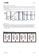
Figure 14. Recommended External Circuit
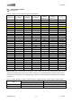
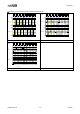
Table 12. Recommended External Components
Items
typ
Unit
Remark
CVM
100
µF
Electrolytic Capacitor
CVM1
0.22
µF
Ceramic Capacitor
CVM2
0.22
µF
Ceramic Capacitor
CHL
0.01
µF
Ceramic Capacitor
CVG
0.1
µF
Ceramic Capacitor
CVDC
0.22
µF
Ceramic Capacitor
RIS1
0.2
Ω
At 1.56[A]setting (@VREF=2.5V)
RIS2
0.2
Ω
At 1.56[A]setting (@VREF=2.5V)
RR1
30
kΩ
At VREF=2.5V setting (@VC=5.0V)
RR2
30
kΩ
At VREF=2.5V setting (@VC=5.0V)
Note 16. Above values are examples. Please choose appropriate external components for your system board.
Note 17. Capacitance of CVM and CVC should be determined in consideration of the load current profile, the
load capacitance, the line resistance and etc. of the actual system board.