
Specification

[AP1034]
016003455-E-01 - 10 - 2016/06
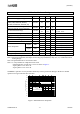
STEP
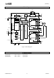
IOUT1
ENABLEB
IOUT2
0%
0%
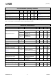
STEP
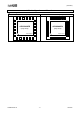
IOUT1
SLEEPB
IOUT2
0%
0%
Max3.0ms
ENABLEB
RESETB
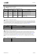
Figure 4. ENABLEB signal Timing Chart
(W1-2 phase)
Figure 5. Sleep Mode Cancel Timing Chart
(W1-2 phase)
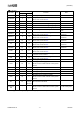
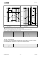
MODE1,MODE2 : Motor Excitation Mode Setting Terminal
The MODE1 and MODE2 terminals are used to configure stepping format as shown below.
Table 4. Settings of MODE terminals that excite motor
MODE1
MODE2
Excitation mode
L
L
2 phase (Full step)
H
L
1-2 phase (1/2step)
L
H
W1-2 phase (1/4step)
H
H
2W1-2phase (1/8step)
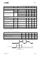
STEP : Step Input Terminal
The sequencer operates at the rising edge of the STEP input, electrical angle will proceed one at each step.
Please design the pattern such that there is no jump of noise in STEP input terminal.
Table 5. Step excitation state against STEP input
STEP
Condition
Rising Edge
Sends excitation step
Falling Edge
Hold excitation step