
Installation Guide
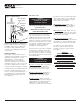

GUIDELINES
FOR UNIT
INSTALLATION
Page 3
Framing Requirements
Due to individual site variations, exact
guidelines for every situation cannot be
supplied. The recommended framing
and dimensional requirements shown
are for a typical application and may
vary, depending on site requirements.
The dimensions shown in Figures 1a and
1b are from the surfaces where the unit
will be attached. This surface can be
bare studding, dry wall or other suitable
underlayment material. It is important
that the floor and all framing be square
and level. Framing should be done
using accepted materials and con-
struction techniques, in accordance
with all applicable codes.
An optional unit cap is available for
selected tub/shower models, which will
require the construction of a header for
proper unit installation. The header is
only required for units using a cap.
Optional Unit Cap Installation
An individual set of installation guide-
lines are included in the optional unit
cap package. The unit cap CANNOT
be properly installed after the unit has
been secured in the framed area.
Refer to, and follow the instructions
packaged with the cap before
continuing.
NOTE: It is advisable to have the unit on
site during the early stages of framing.
NOTE: Any pre-constructed wall may
require modifications or additional
framing members to allow for pipes or
fittings which protrude from the unit on
whirlpool equipped models, for proper
unit installation.
NOTE: A pump access is MANDATORY
on all whirlpool equipped modules.
Additional access areas may be
necessary to comply with code require-
ments. (Figure 1a and 1b)
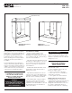
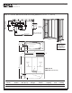
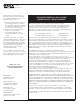
Figure 1b - Unit Data, Dimensional and Alcove Framing Guidelines (Tolerance: +0 / -3/8 inch)
2"
21" W x 16" H
Pump Access
MANDATORY
on All Whirlpool
Equipped Units
89 1/4"
from
Floor
Ceiling
Face of
Header
HEADER DETAIL
2 x 4
2 x 4
Bottom
Plate
Dbl. 2 x 4 Stud
(see plan view)
SBW-3360 R
SBW-3360 L (illustrated)
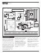
1 1/2"
78 1/2"
17 3/4"
59 1/4"
14 3/4"
60"
2"
1 1/2"
34 1/2"
33"
16 1/4"
16 3/4"
9 1/4"
2 1/2" Dia.
Overflow
2" Dia. Drain
50 3/4"
56"
Elevated
Shelf
Bar
Elevated
Shelf
Soap
Ledge
Lumbar
Support
NOTE: Left End Drain
Installation Illustrated
Fixture
Blocks
Drain Cut-Out
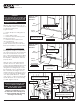
89 1/4"
Cap
Header
Height
Header for Optional Unit Cap
(required only for units installed with optional cap)
Alcove Length
Unit Length
Minimum Alcove Depth
Unit Rough-In Depth
Drain
Center
Drain
Center
Drain
Cut-Out
Drain Cut-Out
Finished Unit Depth
Header for Optional Cap
21" Wide
Standard
Whirlpool
Pump
Access
5"
60"
9 1/4"
12 1/4"
16 1/4"
34 1/2"
33"
13 3/4"
14 1/4"
Unit Sump Bottom Dry Unit Avg. Oper. Max. Sump Base Floor
Model Surface Dim. (W x L) Weight Volume Capacity Area Loading
SBW-3360 Gelcoat 17 X 37 in. 150 lb. 27 gal. 40 gal. N/A N/A
1. Dry unit weight includes whirlpool system.