MVP MANUAL CHAPTER 7. MVP MANUAL 1. INTRODUCTION The multi video processor (hereafter referred to as MVP below) is equipped with a serial interface conforming to RS-232C standards which can be connected to computers. This manual is required when connecting the MVP to the external computer and controlling adjustments and performance. This manual describes the methods of using the RS-232C interface, command protocols, and basic functions and commands of the MVP.
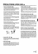
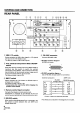
MVP MANUAL 2. CONNECTION WITH MVP EXTERNAL COMPUTER • Refer to Chapter 4.(P.105) “External Control by MPJ RS-232C” for how to adjust the MPJ. ¶ Use a RS-232C straight cable. ¶ Refer to the following diagram for connections. ¶ MVP RS-232C Settings Baud rate Bit number Parity Stop bit : : : : : 2400, 4800 , 9600, 19200 7, 8 NON , ODD, EVEN 1 ,2 Setting at shipment This setting can be changed using the DIP switches on the panel. Refer to “Chapter 2.(P.19) MVP panel 7 Baud rate switch”.
MVP MANUAL 3. INSTRUCTIONS FOR USING A COMPUTER AS A TERMINAL ¶ Use commercially available communications software. ¶ Use PC-DOS internal commands (TYPE, COPY, etc.) Pay attention to use because only one-way transmission of data is possible in this case. ¶ Use commercially available communications software (CCT 98, etc.) ¶ Use the MS-DOS commands (TYPE, COPY, etc.
MVP MANUAL 4. OPERATING MODES 1. Normal mode : This mode is set when the power and reset switches are pressed. This makes the panel switch effective and sets the performance mode according to the switch settings. 2. Operation mode : Mode which enables MVP from the external computer. This mode is set when the ! command is transmitted after connecting the computer. The normal mode can be set according to the command used.
MVP MANUAL 5. Adjustment Mode ¶ NTSC Input Board Adjustment Mode: Mode in which the adjustment commands of the NTSC input board can be executed. (Adjustment items of the output board can be executed when desired) To end the adjustment mode, input AJN. Operation mode AJYC Enables the NTSC input board to be adjusted.
MVP MANUAL 5. MVP VIDEO OUTPUT MODES ¶ The video output formats set by the mode switches are as shown in the following table. (At shipment, the mode switch value is set to “8”.) Mode switch No. Bus format 0 1 2 3 4 5 6 7 8 9 A B C D E F Output format VBS, Y/C NTSC RGB Sync signal frequency Standard speed Dropout reduction function OFF Double speed Reserved VBS, Y/C NTSC RGB Standard speed ON Double speed Reserved ¶ Bus format ¶ Output format : NTSC ..........................
MVP MANUAL 6. ADJUSTMENT FUNCTIONS MVP enables the input and output boards to be adjusted and set by connecting the external computer. The following are items which can be set. (1) MVP settings • For adjusting the picture frame (output image position) (Coarse adjustments:Refer to &P, &Q command, fine adjustment:&G command), and correcting the joinings of the magnified screen.
MVP MANUAL 7. PICTURE FRAME ADJUSTMENT PROCEDURES Adjust the MVP picture frame as follows. (1) Connect the RS-232C cable to the MVP panel. (Refer to (P.141) “Connection with MVP external computer”.) (2) Initialize the picture frame data in RAM. ex. &L0 (Refer to &L command.) (3) Set to the magnified screen to be adjusted. ex. M11C22 ) (@9 (Refer to the M command, @ command.) (4) Perform coarse adjustment of the picture frame. ex. &P21 ++–– (Refer to the &P command.
MVP MANUAL (3) To set the system back to 4-screen magnification [@ command] Input: @h (h=8 or 9) Explanation: • For setting the system back to 4-screen magnification after convergence adjustment, etc. • Used also when the normal 4-screen magnification output cannot be obtained due to incorrect operations, etc. @8 ................... (Sets 4-screen magnification of the OPTION input) ...................
MVP MANUAL (2) To perform coarse adjustments of the picture frame [&P2, &Q2 commands] Input: Explanation: &P2d2h1h2h3, &Q2d2h1h2h3 &P2 command: Horizontal direction &Q2 command: Vertical direction d2 : Screen position (1 to 2) h1h2h3 : crew start position data (&P2:000 to 1C5, &Q2:000 to 20A) Although the data is an absolute value, the relative value with the current data can also be specified.
MVP MANUAL (3) To store the picture frame data [&W command] Input : &W0, &W1 Explanation : &W0 : Sets the saved values to the settings at shipment. (Load data using the &L command.) &W1 : Saves the value adjusted. • The parameters saved by the &W command are as follows. • Picture frame data (Data changed by the &G command.) • Screen start position data (Data changed by the &P2 command and &Q2 command.) • Note : When this command is executed, the setting will be saved even if the power is turned off.
MVP MANUAL 3. To switch the image input [IFF command] Input: IFFa Explanation: Switches between the V IN input 4-screen enlarged display and the OPTION input 4-screen enlarged display.
MVP MANUAL 4. To indicate the current MVP state [SYS command] Input: SYS Explanation: The current MVP state is shown when SYS is input. (Example) RMD-V3000 Series PROGRAM Ver. 1.00A ID 0 This is displayed continuously. MODE 8 DEMO 8 GEN LOCK INTERNAL MANUAL MODE L2 INPUT : V.SCAN BOARD L3 INPUT : NO BOARD L4 INPUT : NTSC BOARD STANDARD MODE VBS L5 INPUT : NO BOARD This is displayed L6 OUTPUT : 4 OUT BOARD countinuously.
MVP MANUAL *6 : Display of remote and manual states REMOTE MODE : Remote state MANUAL MODE : Manual state *7 : Slot number *8 : Type of input board NTSC BOARD : NTSC input board V.SCAN BOARD : Variable scan board (option) NO BOARD : No input board is incorporated *9 : NTSC input board state STANDARD MODE : When standard NTSC signal is input NO STANDARD MODE : When non-standard NTSC signal is input *10: Display of VBS/ Y/C select switch state VBS : Composite video signal input (Indicates V FIL.ON for the V.
MVP MANUAL (3) Bright compensation [BRT command] Input: Explanation: BRTd Corrects the brightness of the NTSC input board. d : Compensation value 0 to F * : Displays the current value and moves to the sub command mode BRTd • To execute this command, it is necessary to set the adjustment mode by AJYC. (Refer to the AJYC command.) • The changed value will be memorized the last. (Example) BRT3 Sets the bright level to 3. *Sub command mode of BRT command .
MVP MANUAL (5) Tint adjustment [TNT command] Input : TNTd1d2d3 Explanation: Corrects the tint of the NTSC input board. : Compensation value 0 to 255 d1d2d3 TNT? : Help display : Displays the current value and moves to the sub command mode TNT • To execute this command, it is necessary to set the adjustment mode by AJYC. (Refer to the AJYC command.) • If data input is skipped, the sub command input mode is set after the data is displayed. The sub command mode is the same as with the COL command.
MVP MANUAL (5) To set the output to the NTSC mode [NT command] (6) To set the output to standard RGB mode [NTR command] (7) To set the output to the double-speed RGB mode [NTD command] Input : NT , NTR , NTD Explanation : • NT : Sets the NTSC input mode. H : 15.734 kHz V : 59.94 Hz Composite video, Y/C output • NTR : Sets the standard speed RGB mode. H : 15.734 kHz V : 59.94 Hz • NTD : Sets the double-speed RGB mode. H : 31.469 kHz V : 59.94 Hz • This command is executed in the remote mode.
MVP MANUAL 8. DEMO PATTERN SETTINGS AND CAUTIONS The MVP does not have an RMD-V3216 type DEMO switch, but 2x2 enlarged screen automatic display is possible by reading the input selector switch (OPTION/V IN) when the power is turned on and executing the command corresponding to that setting. Because of this, upon shipment from the factory command examples for displaying the MVP 2x2 enlarged screens have been written into the demonstration switch No. 8 and No.
MVP MANUAL 9. INSTALLING AND REMOVING BOARDS For your safety ¶ Be sure to turn the power off before installing and removing boards. 1 Remove the front panel. 2 Remove the screws fastening the board to the removed. (Fig. C) 3 Lift the ejectors indicated with white arrows. (Fig. B) 4 Gently draw out the board along the rails. 5 Set the front panel back in place. 1 Remove the screws from the front panel, then open the front panel. (Fig.
MVP MANUAL Lane exclusively for control boards = L1 + Insertion lane Lane exclusively for option boards = L2 + Insertion lane Lane exclusively for input boards = L3 + Insertion lane Lane exclusively for output boards = L4 + Insertion lane Power unit Only service personnel should touch this.
MVP MANUAL 10. RMD-V3020 COMMAND REFERENCE (1) Outline of the RMD-V3020 • Introduction The RMD-V3020 is an input board (hereafter referred to as VS board) which supports variable scanning for inputting images of computer (hereafter referred to as PC) to the MVP. Horizontal frequency : 24 kHz to 35 kHz Vertical frequency : 55 Hz to 72 Hz Dot clock : Up to 35 MHz Signal : Non-interlace signal (The HDTV, 15 kHz RGB signal will not be displayed because it is interlaced.
MVP MANUAL (2) VS board command rules 0. Symbols aaa ddd xxx hh 1. : Command consisting of 3 alphabet letters : Basic commands : Decimals between 0 to 255 consisting of 1 to 3 digits. Can start with 0. Exceptional commands : Depends on each command. : Special data. UP0 to UP9, UPF, DW0 to DW9, DWF, RES. : 2-character hexadecimals between 00 and FF. Basic commands • Executed commands aaa : Executes and ends. ARS, DSN, DSX, DSY, FZN, FZY • Displayed commands aaa : Displays and ends.
MVP MANUAL 2. Exceptional commands • Model data commands TBL : Displays the current model data table. TBLhh : Displays the hh model data table. M : Displays the current model number. Mhh : Sets the hh model number. Fhh : Sets the hh model number data to the initial value. When the hh model data does not exist, “**NO DATA**” is displayed. When hh contains characters other than 0 to 9, a to f, and A to F, “DATA ERROR” is set. • Frequency commands HFQ : Displays the current model determination H frequency.
MVP MANUAL (3) Tracking adjustment [TRK command] Input : TRKd1d2d3 Explanation: • d1d2d3 : Compensation data 0 to 254 • Eliminates lateral vibration of displayed characters, shaking, and noises. TRK adjustment • A vertical line pattern in which the black and white lines change every dot as shown below is the ideal for adjustments. (4) Contrast adjustment [CNT command] Input : CNTd1d2d3 Explanation: • d1d2d3 : Compensation data 0 to 254 • Use this command to adjust the contrast.
MVP MANUAL (7) B, R clamp adjustment [BLV, RLV commands] Input : BLVd1d2d3, RLVd1d2d3 Explanation : • d1d2d3 : Compensation data 0 to 254 • BLV : Adjusts the B clamp level. RLV : Adjusts the R clamp level. • Use this command to adjust so that the white balance of the low light side of the images produced by the MVP matches that of the actual images of the computer. • Tracking may deviate in some cases when clamp level adjustment is performed after TRK adjustment.
MVP MANUAL (10) Horizontal, vertical blanking window position adjustment [HWN, VWN commands] Input : HWNd1d2d3, VWNd1d2d3 Explanation : • d1d2d3 :Compensation data 0 to 254 • HWN :Adjusts the H blanking window position. VWN :Adjusts the V blanking window position. However, the picture inside the blanking window also moves.
MVP MANUAL (12) Full dot number compensation [HFD command] Input : HFDddd Explanation : • d1d2d3:Compensation data 0 to 254 • Corrects the preset sampling clock. • Vertical bit lines can be erased by executing the HFD command. • The HFD and HPS data are correlated and have limited values. Bit lines Figure: Bit Lines which can be Erased by HFD Execution (13) Freeze frame Y:ON N:OFF [FZY, FZN commands] Input : FZY, FZN Explanation : • Continuously outputs the image the moment the FZY is executed.
MVP MANUAL (15) Vertical compression filter conversion rate input [LCV command] Input : LCVd1d2d3d4 Explanation : • d1d2=00 to 15 (Add 0 before all numbers below 9) Vertical direction rate before conversion • d3d4=00 to 15 (Add 0 before all numbers below 9) Vertical direction rate after conversion Due to the use of a compression filter, the condition=is d1d2 > d3d4. Both LCV0000 and LCV0101 are not convertible.
MVP MANUAL (18) To select preset model [M command] Input : Mh1h2 Explanation : • Refer to “VS Board Model Selection” described later for the VS board model selection. • Forcible locks the model data preset. Model data No. h1 h2 0 0 Discriminates the model.
MVP MANUAL (19) Model fresh [F command] Input : Fh1h2 Explanation : • Sets back to the model data preset at shipment. Model data No. h1 h2 0 0 Auto 0 1 VGA (640 x 480) 0 2 IBM-PC (EGA emulation) 0 3 Macintosh 13-inch monitor mode (Standard) 0 4 Macintosh 13-inch monitor mode (RasterOps type) 0 5 Macintosh 13-inch monitor mode (Power Mac) 0 6 FM-R50 0 7 IBM Think Pad 230C 0 8 X68000 0 9 NEC PC9801 (640 x 400 mode) 1 0 Unused area (Do not specify using the M command.
MVP MANUAL (21) Model table reference [TBL command] Input : TBLh1h2 Explanation : hh model data No. (Refer to the M command for the model data No.) • Displays the data table of the model data h1h2 model. When h1h2 is omitted, displays the data table of the model connected to the VS board currently. (Example) : TBL MODEL NO.=09 AUTO (Indicated autolocked to PC98.
MVP MANUAL The relative address and data are as follows. However, relative addresses 20 to 3F are the system reservation range. Relative ADDR 00 01 02 03 04 05 06 07 08 09 0A 0B 0C 0D 0E 0F Data Contents Model data No. Horizontal frequency NNN.
MVP MANUAL (23) Vertical frequency input [VFQ command] Input : VFQd1d2d3.d4d5d6 Explanation : • Directly changes the horizontal frequency of the model data table used for the VS board currently. • Input the frequency using 6-digit decimal numbers. When data input is omitted, the vertical frequency on the current model data table is displayed. Although numbers outside the vertical specification range (55.0 kHz to 72.0 kHz) range of this board can be input, they cannot be used as preset data.
MVP MANUAL 11. MODE 99 The VS board contains preset data for autolocking 9 computer main models at shipment. However, looking at the recent PC market is taken into consideration, it is not possible to incorporate preset data in all models due to the diversification of manufacturers, models, and graphic mode, etc.
MVP MANUAL 12. VS BOARD MODEL SELECTION PC signal input Preset PC? (01 to 09) YES NO Locked in Mode 99? NO YES Output in Mode 99 The model may be outside the application range. Auto locked Check frequency, line number using FRQ command Frame, color adjustment Lock preset model data using M command. When using the Mode 99 data as it is. Description With the VS board, first the input PC frequency and full line number are measured.
MVP MANUAL 14. SELECTING THE SYNC SIGNAL When adjusting the VS board, care must be taken regarding the relation of the priority order of the sync signal. Order of selecting the sync signal The priority order for selecting the sync signal of the VS board is Separate sync > composite sync > Green on sync.