REFERENCE MANUAL
TABLE OF CONTENTS 5. The MPC Software in Detail ............ 29 5.0 DRUM Program vs. KEYGROUP Program........................................... 31 5.1 The File Browser .............................. 33 5.2 The Upper Section ........................... 35 5.3 The Lower Section ........................... 36 5.4 The Grid ........................................... 38 5.5 Main Mode ....................................... 42 5.6 Program Edit Mode .......................... 47 5.7 Program Mixer Mode ...........
1. WELCOME TO THE MPC Thank you for purchasing the MPC. Fusing Akai Professional’s legendary MPC layout and workflow with the power of your computer, MPC Renaissance and MPC Studio are unrivaled instruments for music production.
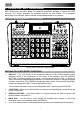
2. OVERVIEW: MPC HARDWARE MPC Renaissance and MPC Studio are hardware specifically designed to control the MPC software. This section describes the hardware controls for each device. For a complete explanation of the software, please read the corresponding chapter of this manual. 2.
6. NUMERIC KEYPAD – If the selected field in the DISPLAY is a number, use these numbered buttons as a standard numeric keypad to enter a value. Press the keypad's ENTER to enter it. 7. UNDO / REDO – Press this button to undo your last action. You can undo up to 200 actions. Hold down SHIFT and press this button to redo the last action you undid. PAD / Q-LINK KNOB CONTROLS 8. Q-LINK KNOBS – Use these touch-sensitive knobs to adjust various parameters and settings.
17. MAIN / TRACK – Press this button to view the Main screen in the display and software. Hold down SHIFT and press this button to view the Track View screen in the display and software. 18. BROWSER / SAVE – Press this button to view the file browser in the display. Hold down SHIFT and press this button to save the current Project (including its samples, Programs, Sequences, and Songs). 19. PROG EDIT / Q-LINK – Press this button to view the Program Edit screen in the display and software.
TRANSPORT / RECORDING CONTROLS 33. PLAY – Press this button to play the Sequence from the audio pointer's current position. 34. PLAY START – Press this button to play the Sequence from its start point. 35. STOP – Press this button to stop playback. 36. REC – Press this button to record-arm the Sequence. Press PLAY or PLAY START to start recording. Recording in this way (rather than using OVERDUB) erases the events of the current Sequence.
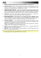
2.2 MPC RENAISSANCE: FRONT PANEL 1 1 1. 2 3 3 4 The front panel of the MPC Renaissance FOOTSWITCH INPUTS – Connect optional 1/4” TS footswitches to these inputs. 2. MIX KNOB – Use this knob to adjust the balance between the MAIN and ASSIGN signals in your headphones. The MAIN signal is the STEREO OUTS. The ASSIGN signal is the ASSIGNABLE MIX OUTS 1 and 2. 3. HEADPHONES – Connect your headphones (not included) to one of these standard TRS outputs (1/8” or 1/4”).
. MIC IN – Connect an external sound source or microphone to these jacks using standard 1/4" TRS or XLR cables. Make sure to set the MIC/LINE SWITCH appropriately. 10. MIC/LINE SWITCH – Set this switch appropriately for the device you connected to the MIC IN jacks. If your sound source is a microphone, set it to MIC. If your sound source is a linelevel device, like an external mixer or keyboard, set it to LINE. 11. PHANTOM POWER SWITCH – This switch activates and deactivates phantom power.
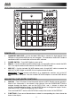
2.4 MPC STUDIO: TOP PANEL 3 13 4 1 2 5 16 16 16 16 17 12 6 6 6 6 6 6 12 24 25 26 27 28 33 34 35 36 37 12 12 18 19 29 30 31 22 15 21 5 47 14 10 8 23 5 7 32 11 46 43 43 45 44 44 20 41 42 40 38 39 The top panel of the MPC Studio. POWER & I/O 1. COMPUTER USB PORT– Use the included USB cable to connect this high-retention-force USB port to an available USB port on your computer. This connection allows MPC Studio to send/receive MIDI and audio data to/from the MPC software. 2.
7. CURSOR BUTTONS – Use these buttons to navigate through the fields of menus and options shown in the DISPLAY. 8. DATA DIAL – Use this dial to scroll through the available menu options or adjust the parameter values of the selected field in the DISPLAY. 9. -/+ – Press these buttons to increase/decrease the value of the selected field in the display. 10. NUMERIC – If the selected field in the DISPLAY is a number, you can press NUMERIC and use the pads as a standard numeric keypad to enter a value.
19. 20. 16 LEVEL – Press this button to activate/deactivate 16 Level. When activated, the last pad that was hit will be temporarily copied to all 16 pads. The pads will now output the same note number as the initial pad, but a selectable parameter will be fixed at the values shown in the diagram on the right, regardless of how hard you hit them. The available parameters are velocity, tuning, filter, layer, attack or decay.
32. WINDOW / FULL SCREEN – When this button is lit, it means the selected field in the display contains additional functions; press this button to access them. Use the FBUTTONS, CURSOR BUTTONS, and DATA DIAL or -/+ buttons to execute (or cancel) these additional functions. Hold SHIFT and press this button to switch between Full Screen and Half Screen modes. In Full Screen mode, the workspace occupies the whole screen.
3. INSTALLING THE MPC SOFTWARE This chapter explains how to install the MPC software including the plugin version on your computer. It also guides you through the process of authorization. 3.1 SYSTEM REQUIREMENTS In order to be able to use the MPC software, you will need at least: Windows PC: • Windows 7 (32- or 64-bit) • 2 GHz Pentium 4 processor or better (multi-core recommended) • 2 GB RAM (4 GB recommended) • 14 GB free hard disk space • Dual Layer DVD-ROM drive Mac: • Mac OS X 10.6.
3.2 INSTALLATION UNDER WINDOWS How to install the MPC software. Installation from DVD: 1. Start your computer and launch your operating system. Insert the MPC DVD into your DVD-ROM drive. If you have enabled the Autostart function in Windows, the Installer will start automatically and you can proceed with Step 5 below. If not, please proceed as follows: 2. Launch the Explorer or open the window "My Computer." 3. Double-click on the icon for the drive that holds the MPC DVD. 4.
3.3 INSTALLATION UNDER MAC OS X How to install the MPC software: Installation from DVD: 1. Disable any system activity monitoring software or extension. Then insert the MPC DVD into your computer’s DVD drive. 2. If required, double click on the MPC icon to open the DVD window. 3. Double-click on the MPC Installer icon to load the installation software. 4. Follow the on-screen instructions. Â After installing the MPC software you need to unlock the program on your computer.
3.4 UNLOCKING THE MPC SOFTWARE You’ll need to unlock your MPC software before using it. Follow these steps to unlock it: 1. 2. 3. 4. 5. 6. 7. 8. 9. 10. 11. 12. 13. Connect your MPC hardware to a USB port on your computer. If you are using MPC Renaissance, connect it to a power source, too. Power on the MPC hardware. Open the MPC software. In the dialogue box that appears, click Unlock Now. Enter your information in the window that appears.
4. QUICK START TUTORIAL This Quick Start Tutorial was written to help you to familiarize yourself with the MPC. In order to get the most out of this tutorial, we recommend reproducing each of the described steps. The MPC hardware display reflects what it's controlling in the software, but due to space and character limitations, the hardware display is slightly different (e.g., parameter names may be abbreviated, the layout may be different or spread across multiple tabs, etc.).
X To create a simple drum set, we repeat the steps described above for other pads. We recommend to load a snare drum on Pad 2, a closed hi-hat on Pad 3 and an open hi-hat on Pad 4. Feel free to add a crash sample to Pad 5. Now you're ready to record a simple drum pattern! 4.3 RECORDING A DRUM PATTERN Let's start to record a drum pattern. X Press the REC button of your MPC hardware to activate the recording mode. To start the actual recording, press the PLAY button.
CORRECT pop-up menu. We recommend to work with 8 or 16 values. Hold down your keyboard's SHIFT and use the ARROW keys to nudge events without restricting to the grid. Hold down the CTRL key (PC) or Command key (Mac) and click-and-drag a note to copy it. Double-click on a note to delete it. Velocity data can be easily edited in the velocity lane below the Grid. Click on a note event (or multiple note events) or place the mouse over a velocity bar in the lane.
4.6 THE BASSLINE TRACK To complete our musical experiment, we need a bassline. In this case, it is important to be able to play a bass sound chromatically. How does that work? First of all, we need to select a new track. Go back to Main Mode and select Track 02 in the TRACK pop-up menu above the Grid. X In the MPC hardware you have to press the MAIN button. With F4 (Track+) you can switch to the next track. This new and empty Track should be assigned to a new Program. You can do this in Program Edit Mode.
Finally, let’s tweak the bassline sound. This can be done in the FILTER section of the Program Edit menu. Back to the MPC hardware! The Filter and Envelope display of the MPC hardware X Press the PROG EDIT button of your MPC hardware to enter Program Edit Mode. Click on the F4 button (Flt Env) to enter the Filter page. X Use the Filter Type option to select a suitable filter type. We recommend to work with the Low 4 type for a start.
4.7 WORKING WITH A DRUM LOOP Modern music producers often use drum loops to add grit and dimension to programmed beats. And this is exactly what we want to do now! Use the FILE BROWSER to locate a drum loop on your hard disk. It is not necessary that it does match the tempo of your recorded tracks. Double-click the desired drum loop so that it is added to the currently selected Program.
You can also edit the note events of the drum loop slices. Enter Main Mode to do this. A new Track with the note events playing their corresponding slices has been automatically created. Use the Time Correct function (i.e., in the Time Correct menu) to quantize the note events to an exact timing. You can also rearrange the note events, thus creating a new playback order for the slices. It is also possible to edit each slice / sample in Program Edit Mode.
The Track Mute display of the MPC hardware X Press the TRACK MUTE button on your MPC hardware to enter Track Mute Mode. X You can now mute a Track by hitting the corresponding pad once. The muted pad is lit red. X If you want to mute a track only at precise note intervals ("quantizing" your mutes, essentially), you can set a musical timing value by clicking on the F4 button (Time Div.). Use the data dial to set a musical value, for example 1 bar. Click on F4 (Close) to close the page.
X Now press F6 (Record) and shout something like "Uhhh" or "Yeah!" into the microphone. The recording procedure starts immediately when the input signal level reaches the threshold value. X Now press F6 (Stop) again, to stop recording. If you're happy with your recording, please name the new sample in the MPC software in the small window, which will pop up automatically after finishing the recording procedure. Let’s call it "Vocal" for now. You should also assign the sample to an unused pad, e.g. Pad 13.
4.10 STEP-BY-STEP WITH STEP RECORDING You’ve already learned how to record note events on a track. But there’s an easier way to do it. The Step Seq mode display of the MPC hardware X It makes sense to use a new track, so use the cursor buttons to navigate to the Trk parameter to select an unused track. Let’s say Track 04. Navigate to the Bars parameter (the number of bars for the sequence) and set it to Bars: 1. X Press the STEP SEQ button on your MPC hardware to enter the Step Seq mode.
4.12 CREATING A SONG In the last few chapters, we have learned how to record tracks. But how can we create a song from our track recordings? The next steps will guide you! Make sure that you have recorded some tracks. All of your tracks combined are called a Sequence. You can create a new Sequence by clicking on the Main tab button and use the SEQ pop-up menu above the Grid to select a new, empty sequence. Within a Sequence, you can record notes and automation data.
5. THE MPC SOFTWARE IN DETAIL The following chapters explain the MPC software in detail. Â Whenever the MPC hardware can be used to control a parameter or a function, this is explained separately in a light-grey box marked by an arrow on its left side. Â We strongly recommend using the MPC hardware to control the software as its intuitive and fast operation will greatly enhance your creative workflow.
Envelope Displays Click on the respective "handle" of an envelope and drag into the desired direction to change an envelope parameter. Pencil/ Select Box Icon Clicking this icon will switch between Draw Mode (Pencil icon) and Select Mode (Select box icon). Draw Mode: • Clicking once on an empty square in the grid will place a note in that square. • Double-clicking a note will erase it. Select Mode: • Clicking and dragging the box over notes on the grid will highlight them.
5.0 DRUM PROGRAM VS. KEYGROUP PROGRAM A Program in the MPC is a file, which contains a list of all samples used, and settings for each sample (i.e., pad assignments, loop points, pitch tuning, effects, etc.) The MPC’s PROGRAM EDIT mode lets you edit and assign samples. The MPC software can hold a total of 128 programs in a Project.
How to set up a KEYGROUP Program Click on the Program Edit tab in the MPC software. Click on the PROG field to open a pop-up menu and choose Add Program. Type a desired program name and choose KEYGROUP as Program Type. Click on OK to create a KEYGROUP program. To load samples into a KEYGROUP program, proceed as follows: X Press the BROWSER button on your MPC hardware. Locate the desired sample and click on F6 (Open) to load it. The sample is now loaded into the current Project. Now press PROG EDIT.
5.1 THE FILE BROWSER The File Browser lets you navigate through your computer’s internal and external hard disks to load samples, sequences, songs etc. Using the predefined and user-definable folders, you can easily adapt the File Browser to your preferred workflow. X To enter the File Browser, press the BROWSER button on your MPC hardware. Within the MPC software, the File Browser can be found in the left area of the application window.
The Browser display of the MPC hardware With the Parent Directory arrow button (in the MPC software, to the right of the data path selector) you can go up one level to the parent directory. FILE directly under the file list window shows the name of the selected file in the list. X Click on the F3 (Play) button to preview any selected audio sample. In the MPC software, the Preview Button is located below the File Browser. Â Keep in mind that only audio samples can be previewed.
5.2 THE UPPER SECTION The Upper section contains the MPC’s tabs as well as further control for selecting Programs, Sequences, Songs, etc. depending on the selected mode tab on the left. This section is always visible. Â The different modes are described in detail in the next chapters. X To select a mode with the MPC hardware, press the corresponding button. To select a mode within the MPC software, click on the corresponding tab.
5.3 THE LOWER SECTION The Lower section contains the overall controls, such as the measure/tempo display and the transport controls. This section is always visible, independent of the selected mode. The CPU meter shows the computer CPU usage of the actual project. Keep in mind that an excessive use of synthesis functions such as filter and effects will increase the CPU usage. Â If the CPU meter is very high, software response may slow down.
STOP will stop the playback. Quickly pressing STOP 3 times will act as a "MIDI panic" and shut off all voices and stop all audio processing. STOP will also stop loading any files that are being loaded. If you select a Project or Program by accident, pressing STOP will cancel loading and clear the loaded files. PLAY will start playback from the current time position. PLAY START will start playback from the beginning of the Song or Sequence or from the First Bar setting.
5.4 THE GRID The Grid is the section where you can record, program and edit your sequences and arrange your songs. The Grid is always visible, independently from the mode selected (except Sample Record Mode and Sample Edit mode). X Click on the SHIFT + WINDOW/FULL SCREEN buttons of the MPC hardware to enlarge the grid. This is ideal for working on tracks and sequences in detail. Â Depending on which type of Program (DRUM or KEYGROUP) is selected, the grid can look different.
X On your MPC hardware, press the MAIN button to edit the described parameters. For selecting a track, use the cursors to navigate to the Trk parameter. You can select the track by using the data dial as well as the -/+ buttons. To change the number of bars, navigate to the Bars parameter. Time Correct and Swing can be edited after pressing the F1 button (T.C.) and setting corresponding Note value and the Swing parameter. To confirm your changes and return to the Main menu, press F5 (Do It).
The Grid View for KEYGROUP Programs When a KEYGROUP Progam is selected, the grid looks as in the following picture. The only difference to the DRUM Program view is the vertical miniature keyboard in the left grid window section. Click on a key to select the corresponding track. You will also hear the note assigned to that key. Everything else works exactly as in the DRUM Programs. How to enter notes and automation data You can easily insert notes and data with your computer mouse.
y Hold down CTRL (PC) or Command (Mac) and move a note to copy it. y Use the copy & paste function to copy a note in the clipboard (CTRL + C (PC) or Command + C (Mac)) and paste it automatically where the audio pointer is with CTRL + V (PC) or Command + V (Mac). Velocity data can be easily edited in the velocity lane (Select and Draw mode): y Click on a note event in the Grid or place the mouse over a velocity bar in the lane. A small round handle will appear at the top of the velocity bar.
5.5 MAIN MODE Main Mode gives you an overview of the most used functions. To enter Main Mode, press the MAIN/ TRACK button on your MPC hardware or click on the Main Tab in the Upper section of your MPC software window. Â Keep in mind that the MPC hardware cannot display as many parameters at the same time as the MPC software. Some of the MPC hardware functions are located in different screens than in the MPC software. Q-LINK Settings Here you can set the functionality of the Q-Link knobs.
touch the top of one the Q-Link knobs, the corresponding parameters will jump to either its minimum (Min) or maximum (Max) value. • In the PAD pop-up menu, you can select the desired Pad / sample you’d like to control. We recommend using Q1 for Pad A01, Q2 for Pad A02 etc., so your controller mapping is easier to remember. • In the PARAM (Parameter) field, you can open a pop-up menu with the parameter you want to assign to the Q-Link knob.
Link knobs, the corresponding parameters will jump to either its minimum (Min) or maximum (Max) value. • In the EFFECT pop-up menu. you can select one of the effects, which have previously been loaded. • In the PARAM (Parameter) field, you can open a pop-up menu with all parameters of the selected effect. The available parameters depend on the chosen effect type. BANK & PAD Selection In the Bank & Pad section, you can easily select a pad to edit. X On the MPC hardware, simply press a pad to select it.
TRACK Settings The Track section gives you an overview of various parameters regarding the selected track. X On the MPC hardware, move the cursor to Trk and use the data dial or the -/+ buttons to select the desired track. You can also click on F3 (Track-) or F4 (Track+) to switch to the desired track or type in the number with the number keys. In the MPC software, click on the TRACK pop-up menu and select the desired track.
Click on the MIDI CH pop-up menu to select the MIDI channel (from 1 to 16) you want to send data on. With the PROGRAM pop-up menu, you are able to send a MIDI Program Change (from 1 to 128) for selecting a particular preset in your MIDI sound generator. When Plugin is selected as the INSTRUMENT: X On the MPC hardware, move the cursor to Pgm and use the data dial or the -/+ buttons to load the desired plugin.
X On the MPC hardware, click on the WINDOW button to open the Edit Current Program display page. Press F2 (Delete) to delete the selected Program. To avoid accidental deletion, a query display opens for confirmation. Press F4 (Copy) to make a copy of the selected Program. This also adds a "-1" to the new Program name. Press F5 (Close) to close the Edit Current Program display page. This can also be done for Sequences (Seq) as well as Tracks (Trk).
MASTER SECTION X To edit the Master section, press the F1 button on your MPC hardware. Use the Q13, Q14, and Q15 Q-Link knobs for direct access of all Master section parameters. Keep in mind that a DRUM program offers fewer parameters than a KEYGROUP program. In the Master section, you can select MONO or POLY mode. In MONO mode, only one pad will sound at a time. If a pad sounds while another or the same one is still sounding, the new sample(s) will immediately cut the sample(s) that are playing.
KEYGROUP PLAY MODES (Keygroup Programs only) Here you can set the behavior for keygroup samples for each pad. X To edit the KEYGROUP PLAY MODES parameters, press the F1 button (Master) on your MPC hardware. Use Q-Link knobs Q9 – Q11 for direct access of all 3 parameters. Keep in mind that these parameters are available only in KEYGROUP programs. You can assign the selected pad to one of the 32 available MUTE GROUPs.
PAN sets the overall stereo placement of the loaded sample(s). With NOTE RANGE, you can restrict the key range used for a sample’s playback. Only notes with a key number higher or equal (LO) or lower and equal (HI) to the selected value will trigger a sound. Set the LO parameter to C-2 and the HI parameter to G8 if you want to use the full keyboard range. The settings for LO and HI are also shown in the virtual keyboard in the EDIT LAYERS section.
range which is input from the respective pad while, for example, a range from 100 to 127 lets the layer respond only to high velocity levels. By assigning several samples of one instrument (e.g., a drum that was hit at different levels) you can create a convincing velocity-layer multisample by adjusting the velocity ranges of each layer accordingly. With ROOT NOTE, you can change the root key of each loaded sample.
FILTER & ENVELOPES SECTION Select the pad you wish to filter by hitting it on your MPC hardware or by selecting it in Main Mode of the MPC software. X To edit the FILTER, FILTER ENVELOPE & AMP ENVELOPE parameters press the F4 button (Flt Env) on your MPC hardware. Use the MPC hardware Q-Link knobs for direct access of all 16 parameters. The Filter Type pop-up menu lets you choose a filter type. A complete list of all filter types can be found in the Appendix of this manual.
The Filter Envelope Edit section in the display of the MPC hardware How does an envelope work? An Envelope creates a variable control signal. It can be used, for instance, to modulate the filter settings of a sound over a given period of time. The classic Envelope comprises four separately controllable parameters: Attack, Decay, Sustain and Release, which is why it is also called ADSR Envelope. Everytime you hit a pad on the MPC, an Envelope is started.
VELOCITY SENSITIVITY SECTION In this section, you set how much velocity effects various sound parameters. X To edit the Velocity Sensitivity parameters press the F5 button (Lfo Mod) on your MPC hardware. Use Q-Link knobs Q9 – Q12 for direct access of all 4 parameters. Keep in mind that a DRUM program uses different dials for controlling than a KEYGROUP program.
CONTROLLER MOD SECTION (Keygroup Program only) In this section, you set the influence of additional play controllers on various sound parameters. X To edit the CONTROLLER MOD parameters, press the F5 button (Lfo Mod) on your MPC hardware. Use Q-Link knobs Q2 – Q4 for direct access of all 3 parameters. Keep in mind that these parameters are available only in KEYGROUP programs. PITCH BEND determines the range of the pitchbend in semitones via a connected MIDI keyboard.
In the MPC software you can load an insert effect by clicking the button at the top of the panel so it reads "On," then clicking on the small triangle on the right of the corresponding insert slot. Select the desired effect from the pop-up menu. To edit the parameters of a loaded effect, click on the effect name to open a window. The effect’s user interface depends on the loaded effect type. Optional VST/AU effects mostly offer a graphical user interface.
5.7 PROGRAM MIXER MODE In Program Mixer Mode, you can set the levels, stereo panning and effects for of each individual pad of a program. If a virtual instrument (PlugIn) is selected, this mode will look different. X To enter Program Mixer Mode, press the PROG MIX button on your MPC hardware. In the MPC software, click on the Program Mixer tab in the Upper section. Â The Program Mixer offers 128 track channels when using a DRUM program (each for every pad).
In the MPC software, click on the desired channel fader and move your computer mouse up and down. Alternatively, you can use your mouse scroll wheel. To view more mixer channels, use the scroll bar below the channel view. X To set the panning for a desired channel, click on the F3 button (Pan) and use the corresponding Q-Link knob for editing. With the PAD BANK buttons you can also select different pad banks to select different sets of 16 channels.
5.8 TRACK MIXER MODE In Track Mixer Mode, you can set the levels, stereo panning and effects for each track. X To enter Track Mixer Mode, press SHIFT + PROG MIX/ TRACK MIX on your MPC hardware. In the MPC software, click on the Track Mixer tab in the Upper section. While the Program Mixer gives you control over the individual pads and its sounds within a program, the Track Mixer is the tool to mix your tracks within a sequence (up to 64 tracks are available).
In the MPC software, click on the Mute button (M) of the desired channel. To view more mixer channels, use the scroll bar below the channel view. If you want to solo a channel, click on the corresponding Solo button (S) to mute all other channels. You can solo as many channels as you like. To deselect solo, click on an active solo button.
Next to the send effects, you have access to 8 submix dials which control the volume of the corresponding submix channel. In the Program Mixer, you can route the audio signal to the desired submix bus. Please read more on this on Page 57. Below the Submix section you can find additional master insert effects. These can be used to apply effects such as Compressor Master or Transient Shaper to finalize your entire mix. Click on the arrow of the slot you want to assign an effect to.
5.9 TRACK VIEW MODE The Track View mode gives you an overview of the tracks of each sequence. Use this mode to edit tracks and sequences simultaneously. X To enter the Track View mode, press SHIFT + MAIN/ TRACK on your MPC hardware. In the MPC software, click on the Track View tab in the Upper section. Depending on what kind of Program is selected, the Track View mode will look different. When a DRUM Program is selected, the Track View displays the drum grid.
5.10 SONG MODE In Song Mode, you can arrange sequences to create songs. X To enter Song Mode, press the SONG button on your MPC hardware In the MPC software, click on the Song tab in the Upper section. In Song mode, you can set an order of sequences and play them subsequently. Song Mode is useful when you are creating a song by combining short sequences. You can edit the structure of a song during playback for easy composing.
sequence to the playlist by dragging and dropping it from a pad onto the list. You can also drag and drop from the pads onto the workspace above them, if you prefer working in a horizontal arrangement. Sequences can be inserted between existing sequences, and by dragging a sequence directly over an another, the existing one will be replaced. The Sequence playlist shows the following information: • The BAR column shows the start measure of a sequence. This depends on the length of the preceeding sequences.
5.11 NEXT SEQUENCE MODE In Next Sequence Mode, you can select sequences to launch them with the pads. X To enter Next Sequence Mode, press the NEXT SEQ button on your MPC hardware. In the MPC software, click on the Next Seq tab in the Upper section. How to add Sequences to the Sequence Playlist You can select the Sequence that you wish to play next by hitting the corresponding pad. This is useful for live performances, as it lets you change a song structure in real time.
The Next Sequence section in the display of the MPC hardware In the MPC software, you will find all parameters to create a sequence playlist in the lower section of the Next Seq mode window. The Playlist window gives you an overview of all used Sequences in your MPC project as well as the number of bars and the tempo of each sequence. In the Pad section, every pad is assigned to a Sequence, starting from Pad A01 with Sequence 1. The selected pad will be green.
5.12 SAMPLE RECORD MODE In Sample Record Mode, you can record audio samples to use them in your tracks and sequences. X To enter Sample Record Mode, press SHIFT + SAMPLE EDIT/ SAMPLE REC on your MPC hardware. In the MPC software, click on the Sample Record tab in the Upper section. Â To record any audio, you need to connect an audio source to your MPC Renaissance or to your computer’s audio interface. Â MPC Studio users: This section describes recording using MPC Renaissance as your sound card.
The Sample Record section in the display of the MPC hardware In the MPC software, the Sample Record section is divided in two main parts. The waveform display shows the waveform of a sample after the recording process. Below is the Record Control section, which offers the controls. In the Q-Link section you can predefine a recording threshold, using Qlink knob Q1. In record-enable mode, the MPC software automatically starts the recording when the level of the incoming source exceeds the threshold.
X To activate the monitor function on your MPC hardware, navigate to Monitor and switch it to ON. The SAMPLE LENGTH display shows you the length of your sample during the recording procedure. This is for control purposes only. Click on the RESET PEAK button to reset the "peak hold", which shows the highest level of your input signal as a red bar within the level meter. X To reset the peak hold on your MPC hardware, press the F1 or F2 button (Reset Peak).
5.13 SAMPLE EDIT MODE In Sample Edit Mode, you can edit samples using various sample editing functions. X To enter Sample Edit Mode, press the SAMPLE EDIT button on your MPC hardware. Use the data dial or the -/+ buttons to select a sample for editing. The selected sample is displayed at the top of your MPC display. In the MPC software, click on the Sample Edit tab in the Upper section.
The Waveform Display The Waveform display shows the entire waveform of a sample, with a start and end point marked as a green line. If either of these lines is moved, the most recently moved one will be red instead of green. The start/end points define the portion of the sample data which will be played. A recorded sample may have a portion of silence at the beginning, which makes it rather difficult to time it correctly when playing it in a musical context. You can fix this by adjusting the start point.
The Sample Edit Controls The lower section offer various controls for editing a selected sample. The EDIT Section This section offers control elements for editing a sample as well as selecting the edit mode (CHOP or TRIM). To read more about the CHOP mode please refer to the end of this chapter. The description below refers to the TRIM mode only. X Use the data dial or the -/+ buttons on your MPC hardware to select a sample for editing. The selected sample name is shown at the top of your display.
The SETTINGS Here you can directly edit various parameters affecting playback and loop functions. X On the MPC hardware, you can edit the sample start, the end and the loop start by navigating with the cursor to the corresponding option (Start, Loop, End). Use the data dial or the -/+ buttons for precise editing. Alternatively, you can enter a value by using the number buttons. Confirm your entry by pressing ENTER.
The Process Sample display for Pitch Shift of the MPC hardware In the MPC software, click on the desired sample editing option. A new window will open. Some options offer additional parameters. To execute a selected option, click on Do It. Otherwise, you can cancel your changes by clicking the Cancel button. Â When the sample edit option window is open, you can click on the Function field to choose another edit option, if desired.
Exp fades the audio out with an exponential curve. An exponential curve will fall quickly in the beginning, and then flatten out as it reaches the end. • PITCH SHIFT changes the pitch of the sample without changing its length. This is useful when you want to change the pitch of the phrase sample in the sequence without changing the tempo. The pitch can be set in a range from + / - 12 semitones. Keep in mind that the audio quality will decrease with more extreme settings.
• Save saves the current sample on your hard disk. A dialog window opens automatically letting you choose a data path for saving. • Rename opens a window to let you rename the selected sample. This doesn’t affect the original sample name. • Edit opens the sample in the waveform display for further editing. The CHOP Mode The Chop function will divide a sample into multiple regions. The MPC software offers three different ways to use this function.
The PAD Section in CHOP Mode In Chop mode you can use the pads for playing back certain portions of the selected sample. The following playback options can be obtained by hitting the corresponding pad: • Play Loop (Pad 13) plays the sample from the loop point to the end point repeatedly. • Play All (Pad 16) plays the whole sample regardless of any editings. • When AUDITION in the SETTINGS section is activated, the pads can be used to play the created slices. Read more about this below.
• With LINK SLICES active, editing the start or end point of a slice will alter the start and end points of its adjacent slices respectively. For example, editing the end point of a slice automatically changes the start point of the following slice. Turn LINK SLICES off when, for example, you want slice 1 to be the entire sample and slice 2, 3 and 4 be just portions of that sample. The CHOP To Section in CHOP Mode This section determines the slicing process.
The PROCESS section in CHOP mode offers an additional option which affects the whole sample regardless of the selected slice. • CONVERT offers three ways of exporting the sliced sample. o Patched Phrase creates a new sample based on your edits done in the Chop mode and places it in the current Project. o Sliced Samples creates single samples of the sliced sample. If Crop Samples is activated, a new sample for each slice is created.
5.14 PAD MUTE MODE In Pad Mute Mode, you can define pad mutes and mute groups for each pad. X To enter Pad Mute Mode, press SHIFT + TRACK MUTE/ PAD MUTE on your MPC hardware. In the MPC software, click on the Pad Mute tab in the Upper section. PAD MUTE Mode You can mute/unmute individual sounds in a particular program on a particular track in real time by hitting the pads.
The PAD GROUP Mode You can set up pad mute groups to mute or unmute multiple pads simultaneously. This is useful when you have several samples assigned to different pads and you wish to mute a group of sounds, or simultaneously isolate a group of specific drum hits. Up to 16 different mute groups can be created. X In the MPC hardware, click on the F2 button (PadGroup) to activate the Pad Group mode. Hit a pad to select it, and use the data dial or -/+ buttons to select the desired group.
5.15 TRACK MUTE MODE In Track Mute Mode, you can define track mutes and track mute groups to use with the pads. X To enter Track Mute Mode, press the TRACK MUTE button on your MPC hardware. In the MPC software, click on the Track Mute tab in the Upper section. TRACK MUTE Mode You can mute/unmute individual tracks in a particular program in real time by hitting the pads.
The TRACK GROUP Mode You can set up track mute groups to mute or unmute multiple tracks simultaneously. This is useful when you wish to mute a group of tracks, or simultaneously isolate a group of specific tracks. Up to 16 different mute groups can be created. X In the MPC hardware, click on the F2 button (TrkGroup) to activate the Track Group mode. Hit a pad to select its corresponding track, and use the data dial or -/+ buttons to select the desired group.
5.16 STEP SEQUENCE MODE In Step Sequence Mode you can create sequences from scratch as well as edit an existing sequence. It also includes further information about your sequence and track settings. X To enter Step Sequence Mode, press the STEP SEQ button on your MPC hardware. Working with Step Sequence Mode in the MPC hardware display In your MPC software, click on the Step Seq tab in the Upper section.
X Press and hold the NOTE REPEAT button to change the time division of the sequence grid. The F-buttons allows you to select the desired value, e.g., with F1 you can select 1/4, with F2 1/8 etc. In the MPC software, you can use the Pad section for step input. Use the TRACK field at the top of the Grid or the TRACK pop-up menu in the TRACK section to select the desired Track first. Click on the PAD field in the Pad section and move the mouse up or down to select the desired Pad you want to edit.
5.17 SOFTWARE MENUS Some of the MPC software’s menu items let you access features that cannot be accessed with the MPC hardware. Â Keep in mind that the menu structure of the MPC software differs between a Windows PC and a Mac computer. Â When loaded as plugin, the Menu button is located to the left of the Main tab. File Menu New Project creates a new empty project. Use this command when you want to start with a new song from scratch. New From Template loads a predefined template project.
If you choose As Audio Mixdown, a separate window opens which offers you the following options: • You can define the length of your audio file by choosing measure Start and End point. This way you can also bounce a certain number of measures only. In addition you can define a the length of a "bounce tail" (Tail) in seconds. This is useful when working with audio effects like reverb or delay which will sound longer than the defined export range.
The Paste command allows you to paste the contents of the clipboard by placing the position marker on a grid location of your choice and perform Paste. The Clear command allows you to delete the content of the clipboard if you no longer need it. Preferences opens the MPC’s Preferences dialog window, which contains many adjustable elements of this application. Click on the corresponding tab in the left windows area to select that page (e.g. Auto Load). Click on the OK button to close the Preferences window.
Parameters of the MIDI Tab The Active Midi Inputs displays the active installed MIDI inputs on your computer system. When the MPC hardware is connected and powered on, the available ports as well as the MPC Public port are displayed. The Midi Mapping lets you define the four Midi Out Port A to D. Here you can select the MIDI output your sequencer data is routed to.
Track Muting is activated, MIDI track volume is sent. This is useful when you want to have the track muted immediately. The advantage of this method is that the loop will continue to play, but at zero volume, allowing the loop to continue playing when the track is unmuted. Using this method, stuttering, beat juggling between two loops, and other DJ style techniques can be employed. • Record Track Mute Events lets you record track mute events.
The Other section in the display of the MPC hardware Pad Curve determines how your playing is translated into velocity values, for example, starting from value A (a soft touch is enough to create a big velocity value) up to D (you have to hit the pad really hard for a high velocity value). With Footswitch 1 and 2, you can select the functionality of a connected footswitch to your MPC hardware. You can either select transport commands (e.g.
• Swing sets the amount of swing. Values range from 50% to 75% and let you shuffle your beats – from subtle to extreme. • Shift Timing will shift the notes by clock ticks. • Window sets the range of notes around a quantize value that will be quantized. Any notes outside that range would not be quantized, whereas notes inside would. • Strength determines how hard notes will be quantized, (i.e., shifted toward the quantize value).
6. APPENDIX In this section, you will find some additional tips and useful information regarding the MPC software. 6.1 EFFECTS & PARAMETERS The MPC software offers various effects for processing samples and sound programs. In the following section, you will find a detailed descriptions how to use effects as well as a list of all available effects and their corresponding parameters with a short explanation of each effect.
Click on the SEND button of the desired channel. Click on one of the SEND knobs of the desired channel and edit its value with your computer mouse. Alternatively, you can use your mouse scroll wheel. Â To use a send effect, you have to load an effect into the corresponding send effect slot to the right of the Track Mixer. Pad effects: The following paragraph explains how to load and edit Pad / Channel effects. X Enter Program Mixer Mode by pressing the PROG MIX button on your MPC hardware.
Mixer, Submix 1 to 8, Out 1,2 to Out 15,16. The outputs that are not available in your audio hardware will show up as greyed out. If a loaded project has outputs routed that don’t exist on your audio hardware, these will shown in red. This can be done in Program Mixer mode by clicking on the arrow above the first insert effect slot. Click on the SEND button of the desired channel. Click on one of the SEND knobs of the desired channel and edit its value with your computer mouse.
The Effect Types: Â Some effects offer a "sync version", e.g. Flanger Sync, which enables the effect to synchronize to the tempo. Flanger A Flanger is an effect that uses a modulated delay line to emulate a classic effect, formerly produced by running two analog tape machines in parallel with a slight time disalignment. Slow rates can produce a jet engine "whoosh" effect, faster rates add a "warble" to the sound. Parameter Value Range Default Value Q-Link No.
Chorus 2-voice Parameter Value Range Default Value Q-Link No. Wet/Dry 0 (DRY) - 100 (WET) 100 (WET) Q9 Delay 0 - 100 20 Q10 Amount 0 - 100 80 Q11 Width 0 - 100 80 Q12 Feedback 0 - 100 50 Q5 Rate 0 - 100 10 Q6 Autopan This effect uses an LFO to move the incoming signal back and forth across the stereo field, creating a somewhat rotary effect. Parameter Value Range Default Value Q-Link No.
Phaser 1 The Phaser is a classic effect, created by ganged multiple all-pass filters to create "notches", or sharp spikes in the frequency spectrum. The frequencies of these all-pass filters are usually modulated by an LFO to create a sweeping sound. Parameter Value Range Default Value Q-Link No. Wet/Dry 0 (DRY) - 100 (WET) 100 (WET) Q10 Rate 0 - 100 10 Q11 Parameter Value Range Default Value Q-Link No.
HP Filter Sweep Parameter Value Range Default Value Q-Link No. Wet/Dry 0 (DRY) - 100 (WET) 80 Q9 Low Frequency 0 - 100 50 Q10 High Frequency 0 - 100 100 Q11 Resonance 0 - 100 33 Q12 Rate 0 - 100 10 Q5 Parameter Value Range Default Value Q-Link No.
HP Shelving Filter This filter differs from the standard filter type, as it attenuates all frequencies after the cutoff point equally. Parameter Value Range Default Value Q-Link No. Frequency 10 – 19999 Hz 1500 Hz Q9 Resonance 0 - 100 0 Q10 Gain -18.0 - 18.0 dB 0.0 dB Q11 Parameter Value Range Default Value Q-Link No. Frequency 10 – 19999 Hz 1500 Hz Q9 Resonance 0 - 100 0 Q10 Gain -18.0 - 18.0 dB 0.
Q4 0 - 100 5 Q8 Gain 1 -18.0 - 18.0 dB 0.0 dB Q1 Gain 1 -18.0 - 18.0 dB 0.0 dB Q2 Gain 2 -18.0 - 18.0 dB 0.0 dB Q3 Gain 4 -18.0 - 18.0 dB 0.0 dB Q4 Delay Mono Delays the original signal for a specified period of time and plays it back over an adjustable period of time. Parameter Value Range Default Value Q-Link No.
Delay LP The LP and HP Delay is identical to the Mono Delay, but they use a resonant filter in the delay line. Parameter Value Range Default Value Q-Link No. Wet/Dry 0 (DRY) - 100 (WET) 50 Q9 Time 2 - 2000 ms 500 Q10 Feedback 0 - 100 50 Q11 Cutoff 0 - 100 50 Q12 Resonance 0 - 100 20 Q5 Parameter Value Range Default Value Q-Link No.
Delay Tape Sync Tape Delay emulates a delay system using an analog tape loop and a series of tape heads to produce an echo effect. This delay type yields a very distinct echo sound, often heard in reggae and dub-style music. Parameter Value Range Default Value Q-Link No.
Pan 2 0 - 100 50 Q7 Pan 3 0 - 100 50 Q8 Damping 0 - 100 100 Q1 Gain 1 0 - 100 25 Q2 Gain 2 0 - 100 25 Q3 Gain 3 0 - 100 25 Q4 Distortion Fuzz This popular effect uses hard clipping of the audio signal, which, at extreme settings, can turn a standard waveform into a square wave, producing a "razor" effect. Parameter Value Range Default Value Q-Link No.
Distortion Custom This effect is a highly customized distortion, capable of a wide range of useable sounds. Parameter Value Range Default Value Q-Link No. Wet/Dry 0 (DRY) - 100 (WET) 100 Q9 Drive 0 - 100 50 Q10 +Soft 5 - 75 5 Q5 +Clip 5 - 50 5 Q6 -Soft 5 - 75 5 Q7 -Clip 5 - 50 5 Q8 Low -18.0 - 18.0 dB 0.0 dB Q1 Mid -18.0 - 18.0 dB 0.0 dB Q2 High -18.0 - 18.0 dB 0.0 dB Q3 Output -18.0 - 18.0 dB 0.
Compressor Opto A compressor is an effect that changes the dynamic range of a signal by automatically reducing its gain. The Opto Compressor is modeled after a vintage compressor type using an optical circuit to control the volume reduction of the input signal. These compressors are usually associated with soft and unobtrusive attack and release characteristics. Parameter Value Range Default Value Q-Link No.
Compressor Master This is the most transparent compressor, able to perform substantial volume adjustments without artifacts. Parameter Value Range Default Value Q-Link No. Wet/Dry 0 (DRY) - 100 (WET) 100 Q9 Attack 0 - 100 50 Q10 Release 0 - 100 50 Q11 Threshold -50 – 0 dB 0 dB Q12 Ratio 1 - 20 1 Q5 Oldskool Off / On Off Q6 Output -6 - 24 dB 0 dB Q7 Reverb Large This is a spatial effect, designed to emulate the sound of a large hall.
Reverb Medium This is a spatial effect, designed to emulate a medium room. Parameter Value Range Default Value Q-Link No. Wet/Dry 0 (DRY) - 100 (WET) 50 Q9 Pre-Delay 1 - 100 50 Q10 Early Reflection 0 - 100 50 Q11 Density 0 - 100 50 Q12 Diffuse 0 - 100 50 Q5 Decay 0 - 100 50 Q6 Lo-Cut 0 - 100 15 Q7 Hi-Cut 0 - 100 10 Q8 Reverb Small This is a spatial effect, designed to emulate a small room. Parameter Value Range Default Value Q-Link No.
Reverb Out Gate This is a hall reverb that has an additional control. The reverb effect is cut off when the output drops below the level set in the OutGate parameter. Parameter Value Range Default Value Q-Link No.
Frequency Shifter A frequency shifter changes the frequencies of an input signal by a fixed amount and alters the relationship of the original harmonics. This can produce a chorus-like effect as well as very crazy artificial timbres. Parameter Value Range Default Value Q-Link No.
6.2 KEYBOARD SHORTCUTS Here you will find all computer keyboard shortcuts for the MPC software.
File Menu Function Command (PC) Command (Mac) New Project CTRL + N COMMAND + N New From Template CTRL + SHIFT + N COMMAND + SHIFT + N Save Project CTRL + S COMMAND + S Open Preferences CTRL + , COMMAND + , Function Command (PC) Command (Mac) Undo CTRL + Z COMMAND + Z Redo CTRL + Y SHIFT + Z Cut CTRL + X COMMAND + Z Copy CTRL + C COMMAND + C Paste CTRL + V COMMAND + V Duplicate CTRL + D COMMAND + D Function Command (PC) Command (Mac) Select All CTRL + A COMMAND + A P
6.3 SPECIFICATIONS Technical overview and specifications of the MPC hardware and software. MPC Renaissance HARDWARE Display 360 x 96 dot graphic LCD w/backlight Dimensions 19.75" x 12.9" x 2.75" (4.9" at max display angle) (W x D x H) 502 mm x 328 mm x 70 mm (124 mm at max display angle) Weight 10.5 lbs. / 4.
MPC Software • Maximum events: unlimited (based on computer’s CPU) • Resolution: 960 pulses per 1/4-note • Sequences: 128 • Tracks per sequence: 128 • Drum pads: 16 (velocity- and pressure-sensitive) • Drum pad banks: 8 • Sync mode: MIDI clock, MIDI Time Code • Transport Controls: MIDI Machine Control • Polyphony: 64 • Dynamic filtering: 1 State Variable Filter per voice (up to 8 pole, depending on type) • Filter types: Low Pass, Band Pass, High Pass, Band Boost, Band Stop, Analog Model
6.5 GLOSSARY To avoid confusion, the terminology in this manual is based on the MPC parameter names. In this glossary you will find the various terms explained. Aftertouch The majority of contemporary keyboards are capable of generating aftertouch messages. On this type of keyboard, when you press harder on a key you are already holding down, a MIDI Aftertouch message is generated. This feature makes sounds even more expressive (e.g., through vibrato).
Controllers can be used for effects such as slowly swelling vibrato, changing the stereo panning position and influencing filter frequency. Cutoff The cutoff frequency is a significant factor for filters. A low-pass filter for example dampens the portion of the signal that lies above this frequency. Frequencies below this value are allowed to pass through without being processed.
MIDI Thru has a special function. It allows the sender to transmit to several receivers. It routes the incoming signal to the next device without modifying it. Another device is simply connected to this jack, thus creating a chain through which the sender can address a number of receivers. Of course it is desirable for the sender to be able to address each device individually. To achieve this, a MIDI channel message is sent with each MIDI event.
There are two kinds of programs that use samples for their sound source: Drum Programs, mostly used for creating drum programs and easy and quick assigning of samples to a pad, and Keygroups Programs. With Keygroup Programs, you can use one sample (or more) and spread it across two or more keys and play the sample chromatically over a keyboard. That way, there is no need to sample every key of, for instance, a piano. Program Change These are MIDI messages that select sound programs.
The length of a sequence can be set from 1 to 999 bars, which would be enough to create an entire song using only one sequence. However, the MPC software has a dedicated SONG mode that lets you chain sequences together to create a song. Song The MPC software has a special song mode that allows you to arrange different sections (verse, chorus, hook, etc.) in order to build a song. Each song can have up to 250 parts and the MPC software can hold 20 songs in its memory.
MPC SOFTWARE MANUAL ADDENDUM v1.1 We're always improving the MPC software! Version 1.1 includes the following features and improvements. Click a feature from the list below to jump to the section of the addendum. NEW FEATURES • Support for Pro Tools: MPC software can now be used as an RTAS plugin in Pro Tools 9 and Pro Tools 10. Pro Tools 10 is recommended for the best performance. • Extensive new options for routing MIDI and audio in Track Mixer mode.
USING MPC AS AN RTAS PLUGIN You can now use MPC software as an RTAS plugin in Pro Tools 9 and Pro Tools 10. When used as an RTAS plugin, MPC software offers the same features and functionality as the standalone software version. Please refer to your Pro Tools documentation for instructions on loading RTAS plugins. ROUTING TRACKS TO SEPARATE OUTPUTS IN TRACK MIXER MODE You can now route your tracks to Submixes or outputs (e.g., Out 1,2) in Track Mixer Mode.
USING BANK SELECT AND PROGRAM CHANGE MESSAGES The MPC software now lets you send Bank Select and Program Change messages. To set these messages, first enter Main Mode, and go to the Instrument section, click the Instrument pop-up menu, and select Midi. • To select a Bank Select or Bank MSB (Most Significant Byte) message, click the Bank pop-up menu, and select the desired message (0-127 or Off).
USING YOUR KEYBOARD TO SWITCH BETWEEN THE SELECT AND DRAW TOOLS You can now use your keyboard to switch quickly between the Select (marquee) and Draw (pencil) tools when editing in the Grid. "1" Click in the Grid to make it active, and then press your computer keyboard's "1" key to select the Draw tool or "2" key to select the Select tool.
EDITING SEQUENCE LOOP PARAMETERS WITH HARDWARE You can now use the MPC hardware to set the Loop parameters of the sequencer. X To edit the sequencer's Loop parameters, press the MAIN button to enter Main Mode, use the cursor buttons to select the Loop field. You can use the data dial or -/+ buttons to select ON or OFF. To edit more parameters, press the WINDOW button.
WWW.AKAIPRO.