
Instruction Manual

IN 2
2/3 CV1V/Oct
IN 3IN 1
INPUT 1
FREQ CV EMP CV
INPUT 2 INPUT 3
EMPHASIS
FREQ-CV OUT
EMP-CV1/3 CV
-2
-4 4
2
TRANSISTOR LADDER FILTER
mod
2
8
4
6
0
10
2
8
4
6
0
10
2
8
4
6
0
10
2
8
4
6
0
10
2
8
4
6
0
10
2
8
4
6
0
10
FREQ
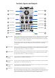
7 Cuto Freq.
9 Freq. CV Level
4 Input 1 Level
11 1/3 CV Input
10 1V/Oct Input
8 Freq. CV Input
1 Audio Input 1
Emph. CV Level 15
2 Audio Input 2
Input 2 Level 5
Input 3 Level 6
2/3 CV Input 12
Emp. CV Input 14
Audio Output 16
Audio Input 3 3
Emphasis Level 13
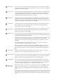
1 Audio Input 1 :
Audio Input 1 forms part of a 3 input audio mixer which is attached to the front end of the
lter. This Input is mixed with Input 2 and Input 3 at a level set by Audio 1 Level control
(4). Typically the output from a VCO would be connected to this Input, but any AC signal
with a level of up to +/- 5 Volts is acceptable. .
All three Audio Inputs are for audio signals only, the lter signal path is AC coupled so DC
control voltages are not useful here but will not cause any problem if accidentally
connected.
2 Audio Input 2 :
Audio Input 2 forms part of a 3 input audio mixer which is attached to the front end of the
lter. This input is mixed with Input 1 and Input 3 at a level set by Audio 2 Level control
(5). Signal levels of up to +/- 5 Volts are acceptable.
3 Audio Input 3 :
Audio Input 3 forms part of a 3 input audio mixer which is attached to the front end of the
lter. This input is mixed with Input 1 and Input 2 at a level set by Audio 3 Level control
(6). Signal levels of up to +/- 5 Volts are acceptable.
4 Input 1 Level :
Sets the amount of signal from Audio Input 1 (between 0% and 100%) that is mixed with
Audio Inputs 2 & 3 and sent to the lter core.
5 Input 2 Level :
Sets the amount of signal from Audio Input 2 (between 0% and 100%) that is mixed with
Audio Inputs 1 & 3 and sent to the lter core.
6 Input 3 Level :
Sets the amount of signal from Audio Input 3 (between 0% and 100%) that is mixed with
Audio Inputs 1 & 2 and sent to the lter core.
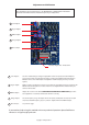
Controls, Inputs and Outputs
7 Cuto Freq. :
The Cuto Frequency control manually varies the cut o frequency of the low pass
lter. At the minimum setting (fully counter clockwise) the lter will cut o all frequencies
with no audio output and at the maximum setting the lter will pass all frequencies. It is
still active when using CV control, in which case it acts as an oset control.
(Audio)
(Audio)
(Audio)