
Specifications


OM-229 158 Page 45
Hardware is common and
not available unless listed.
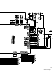
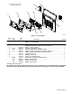
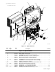
Figure 11-7. Left Windtunnel
804 225-A
2
12
6
13
7
4
11
15
9
3
5
14
8
1
10
Quantity
Description
Part
No.
Dia.
Mkgs.
Item
No.
Figure 11-7. Left Windtunnel
1 216 631 WINDTUNNEL, LH 1... ............. .. ..............................................
2 218 683 HEAT SINK, diode 1... ............. .. ...............................................
3 170 647 BUSHING, snap-in nyl 1.312 ID x 1.500 mtg hole 2... ............. .. ....................
4 025 248 STAND-OFF, insul .250−20 x 1.250 lg x .437 thd 8... ............. .. ....................
5 115 443 STAND-OFF, no 6−32 x .750 lg .250 hex 7... .............. .. ...........................
6 083 147 GROMMET, scr no 8/10 panel hole .312 sq .500 high 2... ............. .. ................
7 RT3 222 327 THERMISTOR, ntc 30 k ohm at 25 deg C 24 in lead 1... ... ..... .. .................
8 030 170 BUSHING, snap-in nyl .750 ID x 1.000 mtg hole 1... ............. .. .....................
9 218 430 COVER, access 1... ............. .. .................................................
10 220 825 BUS BAR, capacitor 4... ............. .. .............................................
11 C7-C10 218 687 CAPACITOR, polyp film 1.35 uf 700 VAC +5% −0% 4... . ... .. ..................
11 C7-C10 225 775 CAPACITOR, polyp film 1.10 uf 700 vac +5% −0% (400 V model only) 4... . ... ..
12 T2 219 002 TRANSFORMER, control 1... .... ..... .. ........................................
13 PC7 239 266 KIT, circuit card assy intrcnct I srce out 1... ... ..... .. .............................
14 PC1 239 708 CIRCUIT CARD ASSY, ps control w/program 1... ... ..... .. .......................
15 212 038 SCREW, M4 − .7 x 8.5 pan hd−phl stl pld slffmg 8... ............. .. .....................