
Specifications


OM-229 158 Page 43
Hardware is common and
not available unless listed.
804 605-B
2
1
6
5
4
3
9
8
10
7
14
12
15
11
17
18
16
13
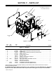
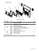
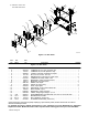
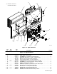
Figure 11-6. Right Windtunnel
Quantity
Description
Part
No.
Dia.
Mkgs.
Item
No.
Figure 11-6. Right Windtunnel
1 216 630 WINDTUNNEL, RH 1... ............. .. ..............................................
2 213 873 HEAT SINK, current source 1... ............. .. .......................................
3 213 871 GROMMET, rbr sil 3.000 ID x 3.250 mtg hole 2... ............. .. .......................
4 170 647 BUSHING, snap-in nyl 1.312 ID x 1.500 mtg hole 1... ............. .. ....................
5 223 120 BLOCK, term 115 amp 3 pole screw term 1... ............. .. ...........................
6 148 743 LUG, univ w/scr 600V 2−14 wire .250 stud 1... ............. .. .........................
7 RT1 222 326 THERMISTOR, ntc 30 k ohm at 25 deg C 34 in lead 1... ... ..... .. .................
8 083 147 GROMMET, scr no 8/10 panel hole .312 sq .500 high 2... ............. .. ................
9 224 391 PANEL, insulating mtg capacitor 1... ............. .. ...................................
10 605 339 WASHER, TOOTH .377 ID X 0.507 OD X .022T stl pld 2... ............. .. ...............
11 PC4 239 240 KIT, circuit card assy intrcnct I srce inpt 1... ... ..... .. ............................
12 212 038 SCREW, M4 − .7 x 8.5 pan hd−phl stl pld 2... ............. .. ...........................
13 176 879 SCREW, M5 − .8 x 12 hex hd−phl 8.8 pld 12... ............. .. ...........................
14 PC8 239 275 CIRCUIT CARD ASSY, bus intrcnct 1... ... ..... .. ................................
15 208 591 SCREW, M 5− .8X 12 soc hd−torx stl pld sems 14... ............. .. ......................