
Specifications


OM-229 158 Page 20
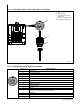
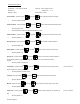
SECTION 5 − COMPONENTS AND CONTROLS
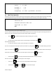
5-1. Controls
When a control panel button is pushed
the yellow lamp lights to indicate ac-
tivation.
1. Power Switch
Use switch to turn power source On and
Off.
2. Power Source Temperature Display
Provides temperature display of the domi-
nant heat sink.
3. KW Output
Provides display of actual power output val-
ue.
4. KW Seconds
Provides display of energy output value.
5. Command Setting
Displays power level programmed by oper-
ator.
6. Degrees C LED
Power source temperature display in de-
grees C when lit.
7. KW Seconds Scaled LEDs
Multiply displayed value by value of lit LED.
8. Fault LED
LED lights to indicate a system fault condi-
tion.
9. Limit LED
LED lights to indicate a system limit condi-
tion.
10. Heat On LED
LED lights to indicate the power source out-
put is energized.
11. Run Button
Use button to run a heating process.
12. Stop Button
Use button to stop a heating process.
13. Cursor Button
Use button to move selection cursor in the
4 x 40 LCD display (item 14.).
14. 4 x 40 LCD Display
Displays programming, runs status, pa-
rameter, fault and limit conditions, and trou-
bleshooting guide.
15. Increase Button
Use button to increase value as required.
16. Decrease Button
Use button to decrease value as required.
17. Parameter Button
Use button to display “real time” power
source operating parameters.
18. Run Status Button
Use button to display “real time” operating
status.
19. Program Button
Use button to program the process control.
804 599-A
1
15
14
13
12
17
16
18
11
8
9
10
7
6
5
4
3
2
19