OM-229 158L 2011−11 Processes Induction Heating Description Induction Heating Power Source Toccotron AC Visit our website at www.AjaxTocco.
TABLE OF CONTENTS SECTION 1 − SAFETY PRECAUTIONS − READ BEFORE USING . . . . . . . . . . . . . . . . . . . . . . . . . . . . . . . . . 1-1. Symbol Usage . . . . . . . . . . . . . . . . . . . . . . . . . . . . . . . . . . . . . . . . . . . . . . . . . . . . . . . . . . . . . . . . . . . . . . . 1-2. Induction Heating Hazards . . . . . . . . . . . . . . . . . . . . . . . . . . . . . . . . . . . . . . . . . . . . . . . . . . . . . . . . . . . . . 1-3.
TABLE OF CONTENTS SECTION 7 − MAINTENANCE . . . . . . . . . . . . . . . . . . . . . . . . . . . . . . . . . . . . . . . . . . . . . . . . . . . . . . . . . . . . . . . . 7-1. Routine Maintenance . . . . . . . . . . . . . . . . . . . . . . . . . . . . . . . . . . . . . . . . . . . . . . . . . . . . . . . . . . . . . . . . . SECTION 8 − SAFETY PRECAUTIONS FOR SERVICING . . . . . . . . . . . . . . . . . . . . . . . . . . . . . . . . . . . . . . . . 8-1. Symbol Usage . . . . . . . . . . . . . . . . . . . . . .
SECTION 1 − SAFETY PRECAUTIONS − READ BEFORE USING ihom _2010−03 Protect yourself and others from injury — read and follow these precautions. 1-1. Symbol Usage DANGER! − Indicates a hazardous situation which, if not avoided, will result in death or serious injury. The possible hazards are shown in the adjoining symbols or explained in the text. Indicates a hazardous situation which, if not avoided, could result in death or serious injury.
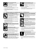
FIRE OR EXPLOSION hazard. INDUCTION HEATING can burn. Do not overheat parts. Watch for fire; keep extinguisher nearby. Keep flammables away from work area. Do not locate unit on, over, or near combustible surfaces. Do not install unit near flammables. Do not operate where the atmosphere may contain flammable dust, gas, or liquid vapors (such as gasoline). After completion of work, inspect area to ensure it is free of sparks, glowing embers, and flames.
1-4. California Proposition 65 Warnings Welding or cutting equipment produces fumes or gases which contain chemicals known to the State of California to cause birth defects and, in some cases, cancer. (California Health & Safety Code Section 25249.5 et seq.) Battery posts, terminals and related accessories contain lead and lead compounds, chemicals known to the State of California to cause cancer and birth defects or other reproductive harm. Wash hands after handling.
SECTION 2 − CONSIGNES DE SÉCURITÉ − LIRE AVANT UTILISATION ihom _2010−03fre Se protéger, ainsi que toute autre personne travaillant sur les lieux, contre les étincelles et le métal chaud. 2-1. Signification des symboles DANGER! − Indique une situation dangereuse qui si on l’évite pas peut donner la mort ou des blessures graves. Les dangers possibles sont montrés par les symboles joints ou sont expliqués dans le texte.
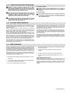
flux, les métaux, les consommables, les revêtements, les nettoyants et les dégraisseurs. Ne pas placer l’appareil sur, au-dessus ou à proximité de surfaces inflammables. Travailler dans un espace fermé seulement s’il est bien ventilé ou en portant un respirateur. Demander toujours à un surveillant dûment formé de se tenir à proximité. Des fumées et des gaz provenant du chauffage peuvent déplacer l’air, abaisser le niveau d’oxygène et provoquer des lésions ou des accidents mortels.
LE RAYONNEMENT HAUTE FRÉQUENCE (HF) risque de provoquer des interférences. Le rayonnement haute fréquence (HF) peut provoquer des interférences avec les équipements de radio-navigation et de communication, les services de sécurité et les ordinateurs. Demander seulement à des personnes qualifiées familiarisées avec des équipements électroniques de faire fonctionner l’installation.
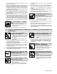
2-6. Informations relatives aux CEM Le courant électrique qui traverse tout conducteur génère des champs électromagnétiques (CEM) à certains endroits. Le courant de soudage crée un CEM autour du circuit et du matériel de soudage. Les CEM peuvent créer des interférences avec certains implants médicaux comme des stimulateurs cardiaques.
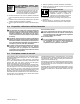
SECTION 3 − DEFINITIONS 3-1. Warning Label Definitions Warning! Watch Out! There are possible hazards as shown by the symbols. 1 1.1 1.2 2 2.1 2.2 3 3.1 3.2 4 4.1 4.2 4.3 5 5.1 6 7 Electric shock from wiring can kill. Wear dry insulating gloves. Do not wear wet or damaged gloves. Disconnect input plug or power before working on machine. Induction heating can cause injury or burns from hot items such as rings, watches, or parts.
3-1. Warning Label Definitions (Continued) 1 2 1 3 2 3 4 5 6 5 4 7 Warning! Watch Out! There are possible hazards as shown by the symbols. Electric shock from wiring can kill. Overuse can cause overheating. Follow rated duty cycle. Disconnect input plug or power before working on machine. Become trained and read the instructions before working on the machine. Connect green or green/yellow grounding conductor to ground terminal. Connect input conductors (L1, L2 And L3) to line terminals.
3-2. Symbols And Definitions Some symbols are found only on CE products.
SECTION 4 − INSTALLATION 4-1. Serial Number and Rating Label Location The serial number and rating information for the power source is located on the front of the machine. Use the rating labels to determine input power requirements and/or rated output. For future reference, write serial number in space provided on back cover of this manual. 4-2.
4-4. Tipping ! Do not move or operate unit where it could tip. 4-5. Electrical Service Guide Failure to follow these electrical service guide recommendations could create an electric shock or fire hazard. These recommendations are for a dedicated circuit sized for the rated output and duty cycle of the welding power source. In dedicated circuit installations, the National Electrical Code (NEC) allows the receptacle or conductor rating to be less than the rating of the circuit protection device.
4-6. Connecting 3-Phase Input Power For 460/575 Volt Models GND/PE Earth Ground 3 8 7 ! Installation must meet all National and Local Codes − have only qualified persons make this installation. ! Disconnect and lockout/tagout input power before connecting input conductors from unit. ! Make input power connections to the welding power source first. ! Always connect green or green/ yellow conductor to supply grounding terminal first, and never to a line terminal.
4-7. Connecting 3-Phase Input Power For 400/460 Volt Models Tools Needed: 3/8 in. 3 = GND/PE Earth Ground 8 10 7 L1 4 9 6 5 3 4 ! Installation must meet all National and Local Codes − have only qualified persons make this installation. ! Disconnect and lockout/tagout input power before connecting input conductors from unit. 1 Select size and length of conductors using Section 4-5. Conductors must comply with national, state, and local electrical codes.
4-8. Power Source Output Connections 1. Output Bus Bars 1 Use supplied 1/4-20 nuts to make electrical connections to the output bus bars as required by the specific application.
4-9. Remote 14 Receptacle RC14 Information and Connections 3 A B K C L N D M E J 1. 2. 3. 4. Plug Threaded Collar Keyway Remote 14 Receptacle RC14 (See Section 4-10) To connect to receptacle, align keyway, insert plug and tighten threaded collar. 4 I H F G 2 1 804 597-A 4-10. Remote 14 Socket Information Socket Socket Information A Remote Contactor B E Remote Output Control Control circuit common. Input command signal (potentiometer wiper or 0 to +10 volts DC). Not used.
4-11. I/O Receptacle RC13 Information And Connections 1. Plug 2. Threaded Collar 3. I/O Receptacle RC13 (See Section 4-12) 3 To connect to receptacle, insert plug and tighten threaded collar. 2 1 804 597-A 4-12. I/O Receptacle RC13 Socket Information Socket No.
4-13. Secondary Insulation Protection ! Connect ground lead(s) between the workpiece and power source to provide proper secondary insulation protection from a short in the output circuit. Secondary insulation protection circuitry automatically shuts down the power source output if a potentially hazardous condition exists at the heating device connected to the power source (e.g.
4-14. 115 Volt AC Duplex Receptacle And Supplementary Protector 1. 115 VAC 2.5 A Single-Phase AC Receptacle RC1 2. Supplementary Protector CB1 (2.5 A) The receptacle supplies nominal 115 volts AC auxiliary power. Maximum output from receptacle is 2.5 amperes. 1 CB1 protects 115 volt receptacle RC1 from overload. If CB1 opens, RC1 does not work.
SECTION 5 − COMPONENTS AND CONTROLS 5-1. Controls 7 6 8 9 10 11 12 13 5 14 15 4 16 2 3 17 18 19 1 When a control panel button is pushed 6. Degrees C LED 1. Power Switch 7. KW Seconds Scaled LEDs Multiply displayed value by value of lit LED. the yellow lamp lights to indicate activation. Use switch to turn power source On and Off. 2. Power Source Temperature Display Provides temperature display of the dominant heat sink. 3. KW Output Provides display of actual power output value.
SECTION 6 − SETUP AND OPERATION 6-1. Safety Equipment 1 2 Wear the operation: following during 1. Dry, Insulating Gloves 2. Safety Glasses With Side Shields DO NOT wear rings, watches, or other metallic items during operation. sb3.1* 1/94 6-2. System Description The Toccotron AC is intelligent to the point that it will automatically adjust output power levels if internal system operating parameters or internal temperatures reach or exceed specific set limits (see Section 9). 6-3.
Possible selections Setup 2: System Lock − Yes/No Control Mode − Timed / Remote / Manual Command − Power / Voltage / Current Max KW: 1−35 Degree Units − F / C Backlight − Yes/No Isolation Detect − Yes/No Time Resolution − press the Increase or Decrease button to select the desired time resolution. The factory default is seconds. or Decrease KW Second Alarm − press the Increase button to select the desired KW Second Alarm. The factory default is No.
Backlight − press the Increase or Decrease The factory default is On. Isolation Detect− press the Increase button to turn LCD display backlight On or Off. or Decrease button to enable or disable this feature. The factory default is Yes. All parameters in System Setup are considered global, and any changes to the system set-up parameters will apply to all programs. To reset the system back to factory default settings, turn off the power source, and wait until the display goes blank.
Mode....: Remote Power..: 0.0 KW Run Time:>00:03:00 Current: 0 A Voltage: 0 V Frequency: 4.5 KHz Time is the only parameter that can be set. The values are 0 − 99:59:59 or infinity. 6-4-3. Manual Control Manual control allows programming of a specific power level for a specific period of time. When this process is selected, the following screen appears on the display: Mode....: Manual Power..: 0.0 KW Command.: Current: 0 A Voltage: 0 V 0.0 KW Run Time: 00:03:00 Frequency: 4.
6-5-1. Time Based Control Mode...: Timed Segment KWS: Program: 1 Segment: 1 0 x1 Type...: End Power..: 0.0 KW SegmentTime: 00:00:00 Mode displays the control mode. Also displayed are the present program number, program segment, KW seconds, Segment type, current power level and elapsed time of the current segment. 6-5-2. Remote Control Mode.....: Remote Power....: 0.0 KW CycleTime: 00:00:00 Status...
Power....: 0.0 KW Current..: 0 A Voltage..: 0 V Frequency: 4.5 KHz CycleTime: 00:00:00 6-7. Real-Time Operation Each time the unit is first turned On it initiates a system check routine that includes verification of communication between circuit boards and checking for output isolation faults. During this check routine, all displays and LEDs illuminate and the following screen appears on the display: TOCCOtron AC Firmware Revision OEM 0.52 Copyright (c) 2006 MEM X.
Press the Run button to resume program operation and the yellow indicator LED will illuminate. Press the Stop button to end the program. SECTION 7 − MAINTENANCE 7-1. Routine Maintenance ! = Check = Change = Clean * To be done by Factory Authorized Service Agent Disconnect power before maintaining. Maintain more often during severe conditions.
SECTION 8 − SAFETY PRECAUTIONS FOR SERVICING Protect yourself and others from injury — read and follow these precautions. 8-1. Symbol Usage OM-___ - Date, safety_ihtm 2010−03 DANGER! − Indicates a hazardous situation which, if not avoided, will result in death or serious injury. The possible hazards are shown in the adjoining symbols or explained in the text. Indicates a hazardous situation which, if not avoided, could result in death or serious injury.
MOVING PARTS can injure. Keep away from moving parts such as fans. Have only qualified persons remove doors, panels, covers, or guards for maintenance and troubleshooting as necessary. Keep hands, hair, loose clothing, and tools away from moving parts. Reinstall doors, panels, covers, or guards when maintenance is finished and before reconnecting input power. ELECTRIC AND MAGNETIC FIELDS (EMF) can affect Implanted Medical Devices.
SECTION 9 − DIAGNOSTICS & TROUBLESHOOTING The Toccotron AC power source has on-board capabilities to aid in troubleshooting problems should any conditions occur during operation. This troubleshooting capability consists of the Fault LED, Limit LED, and message screens that appear on the front panel LCD display. 9-1. Operator Interface Indicators 1 2 3 804 599-A 1 Fault LED LED lights to indicate a system fault condition. 2 Limit LED LED lights to indicate a system limit condition.
Pressing the Decrease button will acknowledge the limit and continue operation with the existing setup. In the acknowledge state, the yellow Limit LED will stop flashing and remain on continuously. The LCD display will revert to an active screen once the Program button, or Parameters kW A V Hz button, Run Status button is pressed. If a new limit condition should occur after the first is acknowledged, the yellow Limit LED will start flashing to indicate a new problem.
Fault Condition Additional Information F62: Isolation Fault Check for exposed conductor Clean for moisture on cables F63:Line Voltage Fault Check line voltage F64: Power Source Overtemp Fault Verify power source vents and wind tunnel are unobstructed F65: Current Source Fault Service required F66: Under Frequency Fault Check for loose or open connections in output cable Decrease number of turns Decrease coil space F67: Over Frequency Fault Verify heating cable properly wrapped Verify material b
VLnA-B − This is the approximate phase to phase line voltage between phases A and B. VLnB-C − This is the approximate phase to phase line voltage between phases B and C. VLnC-A − This is the approximate phase to phase line voltage between phases C and A. VBus − This is the DC bus voltage. Therm1 − This is the temperature of the current source primary heatsink. Therm2 − This is the temperature of the bridge heatsink. Therm3 − This the the temperature of the current source secondary heatsink.
9-7. Removing Wrapper and Measuring Input Capacitor Voltage ! 900 Volts dc can be present on the capacitor bus and significant DC voltage can remain on capacitors after unit is Off. Always check the voltage on inverter assembly as shown to be sure the input capacitors have discharged before working on unit. ! Turn Off welding power source, and disconnect input power. ! Significant DC voltage can remain on capacitors after unit is Off.
9-8. Blowing Out Inside Of Unit ! Turn Off welding power source and disconnect input power. ! Remove wrapper and be sure input capacitors are discharged. Blow out inside of unit. Blow out fan motors in right side panel and front panel.
SECTION 10 − ELECTRICAL DIAGRAM Figure 10-1.
219 029-B OM-229 158 Page 37
SECTION 11 − PARTS LIST Hardware is common and 3 5 not available unless listed. 4 See Figure 11-3 12 10 9 1 7 11 6 8 See Figure 11-2 11 2 Figure 11-1. Wrappers Item No. Dia. Mkgs. Part No. Description 804 601-B Quantity Figure 11-1. Wrappers . . . 1 . . . . . . . . . . . . +217 470 . . . 2 . . . . . . . . . . . . . 217 860 . . . 3 . . . . . . . . . . . . +217 325 . . . 4 . . . . . . . . . . . . . 147 876 . . . 5 . . . . . . . . . . . . . 217 334 . . . 6 . . . . . . . . . . . . .
Hardware is common and 4 3 1 11 not available unless listed. 5 2 7 8 10 9 Figure 11-2. Front Panel Item No. Dia. Mkgs. Part No. Description 804 602-B Quantity Figure 11-2. Front Panel . . . 1 . . . . . . . . . . . . . 217 323 . . ... 2 ........................ . . . 3 . . . . . . . . . . . . . 216 224 . . . . . 4 . . PC10 . . . . 239 271 . . . . . 5 . . . PC2 . . . . . 229 148 . . . . . 7 . . . . S1 . . . . . 244 920 . . . . . 8 . . . . . . . . . . . . . 252 731 . . . . . 9 . . . . . . .
1 Hardware is common and not available unless listed. 2 3 4 20 19 5 16 15 18 17 14 13 12 6 7 8 9 10 11 804 603-A Figure 11-3. Rear Panel Item No. Dia. Mkgs. Part No. Description Quantity Figure 11-3. Rear Panel ... ... ... ... ... ... ... ... ... ... ... ... ... ... ... ... ... ... ... ... 1 2 3 4 5 6 7 8 9 10 11 12 13 14 15 16 17 18 19 20 . . . . . . . . . . . . . 217 324 . . . . . . . . . . . . . 224 042 . . . . . . . . . . . . . 170 391 . . . . . . . . . . . . . 220 824 . . . .
Hardware is common and 14 not available unless listed. 1 4 14 12 3 6 2 5 10 13 3 7 6 9 16 15 8 Figure 11-4. Base w/Components Item No. Dia. Mkgs. Part No. Description 804 221-D Quantity Figure 11-4. Base w/Components . . . 1 . . . . . . . . . . . . . 217 328 . . . 2 . . . . . . . . . . . . . 213 865 . . . 3 . . . . . . . . . . . . . 213 939 . . . 4 . . L1,L2 . . . . 218 692 . . . 5 . . . . . . . . . . . . . 216 815 . . . 6 . . . C1,2 . . . . 213 870 . . . 7 . . . . T1 . . . . .
Hardware is common and 13 14 not available unless listed. 7 13 8 10 1 9 4 3 5 6 11 12 2 Figure 11-5. Top Windtunnel Item No. Dia. Mkgs. Part No. Description 804 604-B Quantity Figure 11-5. Top Windtunnel . . . 1 . . . . . . . . . . . . . 218 424 . . . 2 . . . . . . . . . . . . . 218 684 . . . 3 . . . . . . . . . . . . . 025 248 . . . 4 . . . RT2 . . . . . 222 327 . . . 5 . . . . . . . . . . . . . 083 147 . . . 6 . . . . . . . . . . . . . 605 339 . . . 7 . . . . . . . . . . . . .
18 1 Hardware is common and not available unless listed. 2 17 5 6 4 7 15 16 13 8 9 10 3 11 14 12 804 605-B Figure 11-6. Right Windtunnel Item No. Dia. Mkgs. Part No. Description Quantity Figure 11-6. Right Windtunnel ... ... ... ... ... ... ... ... ... ... ... ... ... ... ... 1 2 3 4 5 6 7 8 9 10 11 12 13 14 15 ............. ............. ............. ............. ............. ............. . . . RT1 . . . . . ............. ............. ............. . . . PC4 . . . . . ......
Item No. Dia. Mkgs. Part No. Description Quantity Figure 11-6. Right Windtunnel (Continued) . . . 16 . . . . . . . . . . . . . 229 728 . . . 17 . . . . . . . . . . . . . 030 170 . . . 18 . . . . . . . . . . . . . 231 050 . . . . . . PLG64,410, 411 . . . . . . 115 093 . . . . . . . . PLG47 . . . . 115 091 . . . . . . PLG45,61 . . 131 204 . . . . . PLG111, 112 121, 132, 141, 142 . . . 131 054 . . STRAP, connecting . . . . . . . . . . . . . . . . . . . . . . . . . . . . . . . . . . . . . . . . . . . . .
Hardware is common and 12 not available unless listed. 1 10 8 2 6 13 7 14 3 15 5 4 11 9 804 225-A Figure 11-7. Left Windtunnel Item No. Dia. Mkgs. Part No. Description Quantity Figure 11-7. Left Windtunnel ... ... ... ... ... ... ... ... ... ... ... ... ... ... ... ... 1 2 3 4 5 6 7 8 9 10 11 11 12 13 14 15 . . . . . . . . . . . . . 216 631 . . . . . . . . . . . . . 218 683 . . . . . . . . . . . . . 170 647 . . . . . . . . . . . . . 025 248 . . . . . . . . . . . . . . 115 443 . . . .
Item No. Dia. Mkgs. Part No. Description Quantity Figure 11-7. Left Windtunnel (Continued) . . . . . . . PLG16, 121,122 . . . 131 054 . . . . . . . PLG19, 120 . . . . . . 115 094 . . . . . . . PLG15, 118 . . . . . . 115 093 . . . . . . . PLG77, 119 . . . . . . 115 092 . . . . . . . . PLG17 . . . . 115 091 . . . . . . . PLG18, 116 . . . . . 131 056 . . . . . . . PLG13, 113 . . . . . 162 382 . . . . . . . . PLG14 . . . 130 203 . . HOUSING RCPT+SKTS,(SERVICE KIT) . . . . . . . . . . . . . . . . . . . . .
Warranty Effective January 1, 2011 (Equipment with a serial number preface of MB or newer) This limited warranty supersedes all previous manufacturers warranties and is exclusive with no other guarantees or warranties expressed or implied. 6. LIMITED WARRANTY − Subject to the terms and conditions below, warrants to its original retail purchaser that new equipment sold after the effective date of this limited warranty is free of defects in material and workmanship at the time it is shipped from factory.
Owner’s Record Please complete and retain with your personal records. Model Name Serial/Style Number Purchase Date (Date which equipment was delivered to original customer.) Distributor Address City State Zip Resources Available Always provide Model Name and Serial/Style Number.