
User's Manual


uMAXe Installation Guide
Page 40 Commercial in Confidence UGD-D00218 Rev A
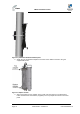
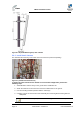
Warning: Mount the junction box in an orientation such that the cable ports
(located on the bottom) face downwards. This prevents rain water from
settling on the ports, thereby, avoiding damage.
Figure 25 - Junction box with mounting brackets assembled
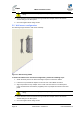
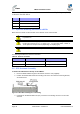
For either mounting method, the mounting bracket provides mounting holes (displayed below):
Figure 26 - mounting bracket (2 required)
5.8.1 Junction Box Installation
To install the junction box:
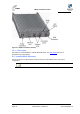
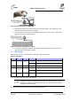
1. Prior to installation connect the 2 mounting brackets to the back of the junction box
fastening to the provided holes. The wall mounting hole orientation should be towards the
outer edges of the junction box.
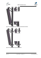
2. Remove the junction box‟s cover, leaving the rubber gasket in place.
3. Prepare the cables for connection by performing the following:
a. Strip about 25.4 mm (1 inch) of the outer jacket of the cable to expose the wires.
b. Using a wire-stripping tool, expose about 6.3 mm (0.25 inch) of each of the wires by
stripping the wires‟ insulation.
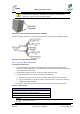
4. Determine which cable entry holes are to be used and remove the appropriate plug.
Table 20 - Cable hole sizes
Cable Entry hole determination
Gland hole PG11 (M18) for cable terminating at MicroMAXe
Gland hole PG29 (M36) for cable 12AWG x6
Gland hole PG16 (M22) for cable 14AWG x2
Note: Save the rubber grommets from the plugs to be used on the weatherproof
glands (connectors).