
User's Manual


uMAXe Installation Guide
Page 39 Commercial in Confidence UGD-D00218 Rev A
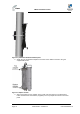
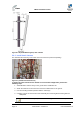
Figure 23 - Attach GPS antenna to RG58 cable
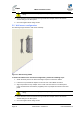
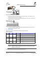
4. Slide the flat washer up to the underside of the mounting bracket, then thread 1 nut onto
the GPS antenna threaded base and tighten.
5. The second nut is then secured and tightened against the first nut to create a clamp load
against the first nut, as shown below:
Figure 24 - GPS antenna assembled on bracket
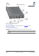
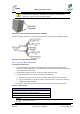
6. Connect the RG58 cable attached to the GPS Lightning/Surge protector (required) to the
GPS connection on the bottom uMAXe.
5.7 LED Display
When powering up refer to the following for indication of BS current status:
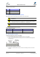
Table 19 - LED Display
LED
Name
Color
Status
Description
PWR
Power
Green
On
Power on
Off
Power off
ALM
Alarm
Red
On
Alarm detected
NML
Network
Link
Green
Steady on
Network link detected
Blinking
Traffic currently flowing
STA
In
service
Green
On
Software running
5.8 Install Junction Box (Optional)
Note: Contact Airspan customer-service to determine whether junction box
installation is required. Installation may be required, depending on the distance
between the external power-supply and the BS, as well as the minimum voltage
supplied by the power-supply.
The Junction box (optional) can be pole-mounted or wall-mounted.