UGD-D00218 Rev A uMAXe Installation Guide System Release 9.
uMAXe Installation Guide Copyright © Copyright by Airspan Networks Inc., 2011. All rights reserved worldwide. The information contained within this document is proprietary and is subject to all relevant copyright, patent and other laws protecting intellectual property, as well as any specific agreements protecting Airspan Networks Inc. rights in the aforesaid information.
uMAXe Installation Guide Table of Contents Copyright .......................................................................................................................................... 2 Table of Contents ............................................................................................................................. 3 Summary of Figures ......................................................................................................................... 5 Summary of Tables ..........
uMAXe Installation Guide 4.1 Verify Safety Requirements ............................................................................................ 22 4.1.1 4.2 5 Warning of Hazardous Voltages ............................................................................. 22 Verify Installation Requirements ..................................................................................... 23 4.2.1 Verify the Tools ......................................................................................
uMAXe Installation Guide Summary of Figures Figure 1 – uMAXe –network interface ............................................................................................ 18 Figure 2 – each sector connected separately ................................................................................ 19 Figure 3 – uMAXe Functional Components ................................................................................... 20 Figure 4 – Workflow of Installation .............................................
uMAXe Installation Guide Summary of Tables Table 1 - uMAXe FCC Maximum Output TX Power ....................................................................... 12 Table 2 - uMAXe ETSI Maximum Output TX Power ...................................................................... 12 Table 3 - Power Consumption ........................................................................................................ 12 Table 4 – 1.4 GHz Antenna Types -Technical ...................................................
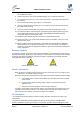
uMAXe Installation Guide Warnings and Cautions Human Exposure to Radio Frequencies The uMAXe antennas should be installed and operated from a minimum distance of 2.4 meters (for 3.x) or 3.4 meters (for 2.x or 1.x) from your body. Radio Interference This uMAXe generates, uses, and can radiate radio frequency energy and, if not installed and used in accordance with the instructions, may cause harmful interference to radio communications.
uMAXe Installation Guide 4. Warning: High voltages exist inside the product - do not remove the lid or base: No user serviceable parts inside. 5. Position the power cord to avoid possible damage; do not overload wall outlets. 6. Do not place this product on or near a direct heat source, and avoid placing objects on the terminal. 7. Do not operate this device near water or in a wet location. 8. Use only a damp cloth for cleaning. Do not use liquid or aerosol cleaners. Disconnect the power before cleaning. 9.
uMAXe Installation Guide be connected to the grounding system of the building, as close to the point of cable entry as is practical. Lightning Protection WARNING: The following notes are general recommendations for the system. The wireless equipment should be installed by a qualified professional installer and must follow local and national codes for electrical grounding and safety.
uMAXe Installation Guide DECLARATION OF CONFORMITY European Community, Switzerland, Norway, Iceland, and Liechtenstein Declaration of Conformity with Regard to the R&TTE Directive 1999/5/EC English: This equipment is in compliance with the essential requirements and other relevant provisions of Directive 1999/5/EC. Deutsch: Dieses Gerät entspricht den grundlegenden Anforderungen und den weiteren entsprecheneden Vorgaben der Richtlinie 1999/5/EU.
uMAXe Installation Guide FCC Notice Federal Communication Commission Notice This equipment has been tested and found to comply with the limits for a Class A digital device, pursuant to part 15 of the FCC Rules. These limits are designed to provide reasonable protection against harmful interference when the equipment is operated in a commercial environment.
uMAXe Installation Guide Maximum Output TX Power Table 1 - uMAXe FCC Maximum Output TX Power Frequency Band FCC TX Antenna Gain EIRP 1.4 GHz 33dBm pending pending 2.3 GHz 36.12dBm 54.12dBm 18dBi 3.65 GHz 36.08dBm 38.
uMAXe Installation Guide OMNI Directional pending pending pending Table 5 - 2.x GHz Antenna Types - Technical Type Frequency range Gain Part number 60° Dual Slant X-Polar 2.3-2.7 GHz 18.0 dBi SEC60X-2.X-RC-1 90° Dual Slant X-Polar 2.3-2.7 GHz 17.0 dBi SEC90X-2.X-RC-1 Omni 10dBi Vertical External 2.3-2.49 GHz 10 dBi ANT2300OV10-360 Table 6 - 3.x GHz Antenna Types - Technical Type Frequency range 60° Dual Slant X-Polar 3.3 - 3.8 GHz 18.0 dBi SEC60X-3.5-RC-1 90° Dual Slant X-Polar 3.
uMAXe Installation Guide 3.65 GHz 2 60º 3.3-3.8 GHz 60º Dual Slant XPolar -4º tilt - mounting included 3.3-3.8 GHz 60º Dual Slant XPolar 0º tilt - mounting included 1 3.65 GHz 2 60º 1.4 GHz 2 90º 1390-1435 MHz 90° 12.5 dBi Dual X-Polar - mounting included - pending 1 2.3 GHz 2 90º 1 3.65 GHz 2 90º 3.65 GHz 2 90º 2.3-2.7 GHz 90° Dual Slant XPolar - mounting included 3.3-3.8 GHz 90° Dual Slant XPolar -4º tilt - mounting included 3.3-3.
uMAXe Installation Guide 1 About this Guide This section discusses the purpose, intended audience, conventions, referenced documentation and organization for this guide. 1.1 Purpose This guide provides the workflow and step-by-step procedures for installing the uMAXe. These procedures include: Verify Prerequisites Install the uMAXe Connect and Manage Cables Set Power System 1.2 Intended Audience This guide is intended for persons who are responsible for installing the uMAXe.
uMAXe Installation Guide Set Power System Appendixes [Review Job Sheet, Securing the cables, Glossary of Terms, Installation Checklist, Contact information and Revision history] Page 16 Commercial in Confidence UGD-D00218 Rev A
uMAXe Installation Guide 2 Introduction This section provides a descriptive overview of the uMAXe and its place in the product suite. 2.1 uMAXe uMAXe is a highly integrated macro-cell base station with all-in-one packaging of RF and baseband components. uMAXe includes integrated dual RF transceivers to support dual channel diversity and MIMO. It is available as an all outdoor solution for Mobile WiMAX applications to minimize physical footprint and operator OPEX.
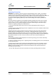
uMAXe Installation Guide Note: The following is for illustration only; actual layout may differ as infrastructure is installation-specific. Note: uMAXe must be properly grounded according with NEC and other local safety code requirements. Note: Installation of the GPS Lightning/Surge protector (ordered separately) is necessary to protect the GPS antenna.
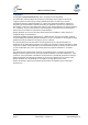
uMAXe Installation Guide Figure 2 – each sector connected separately Note: uMAXe can also be connected via a LAN Switch for greater Failsafe protection. Note: Auto-negotiation must always be enabled on the core network side. Note: Illustrations above displays the GPS mounted directly to the top of the units there is also an option to mount the GPS antennae remotely. The uMAXe is a fully integrated all outdoor base station sector that contains all RF, Baseband and GPS Synchronization functionality.
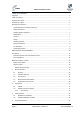
uMAXe Installation Guide Figure 3 – uMAXe Functional Components Page 20 Commercial in Confidence UGD-D00218 Rev A
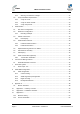
uMAXe Installation Guide 3 Getting Started 3.1 Workflow of Installation The Workflow to install the uMAXe is shown in the following diagram: Figure 4 – Workflow of Installation Caution: Antennas 1 & 2 Tx/Rx must be connected and attached before uMAXe is powered on. 3.2 uMAXe Installation Checklist Plan the installation of the uMAXe by using the Installation Checklist, which you can find as a removable job aid in Appendix A for this guide.
uMAXe Installation Guide 4 Verify Prerequisites Prior to installing the uMAXe, verify the required safety, power, tools, parts and components. Reference: Set up requirements for the installation is detailed in the Job Sheet, see Appendix A for this guide. 4.1 Verify Safety Requirements Read and follow all warning notices and instructions marked on the product or included in this manual.
uMAXe Installation Guide 4.2 Verify Installation Requirements 4.2.1 Verify the Tools Table 9 - uMAXe installation tools Tool Large Crosshead Screw driver Phillips # 3 or Pozidrive # 3 Small flat blade screwdriver Medium flat blade screwdriver 13mm or 1/2 inch open ended spanner 10mm or 13/32 inch open ended spanner Wire strippers Wire cutters Ring terminals crimp tool RJ45 crimp tool 4.2.
uMAXe Installation Guide UMAXE Base Station parts Consisting of Wall mounting kit 1 x Rear panel – PN 402-00-118 (ordered separately) 1 x Top adaptor – PN 402-00-119 1 x Bottom adaptor – PN 402-00-120 2 x Screw M12x180 DIN 933 – PN 501-02-034 4 x Spring washer M12 DIN 127B – PN 501-04-007 4 x Flat washer M12 DIN 125 – PN 501-04-006 2 x Nut M12 DIN 934 – PN 501-03-003 4 x SEMS screw M8x20 with 2 washers – PN 501-05-011 Pole mounting kit Dia.60 – 120mm – plus fixing accessories.
uMAXe Installation Guide UMAXE Base Station parts Consisting of Outdoor power converter for 3.x GHz Type-IC DC Power Cable Available either in - 10, 15 or 30 meter lengths. Additional lengths available. Multimode fiber pigtail cable (not included) (optional) (ordered separately) Multimode fiber pigtail cable – ODC - LC connector. Terminates the outdoor fiber cable and provides an indoor LC connector. 2 meter length.
uMAXe Installation Guide Table 12 - uMAXe wall mount installation parts Parts Images 1 Rear panel 1 Top adapter 3 Bottom adapter 4 GPS Antenna mounting bracket (shown with GPS attached) (pre-assembled) Table 13 - uMAXe pole mount installation parts Parts Images Note: in addition to the Wall mounting kit.
uMAXe Installation Guide Parts Images 2 Filter (Cavity filter) (for 2.
uMAXe Installation Guide Optional Junction Box Consisting of 2x pole bands (stainless steel), as required, supplied. 78 – 102 mm (4”) Mounting screws – for mounting brackets to junction box. EJOT WN1412 – K50 x 12 – 4 supplied. Wall mounting fasteners Hole size = 7 mm Sufficient cable wires ties, as required (not supplied - customer responsibility) 4.2.3 Verify Components uMAXe is shown below from the Ethernet termination and RF port end views respectively.
uMAXe Installation Guide connects the GPS directly to the top of uMAXe. The cable assembly for the remote GPS antenna is shown below. Figure 7 – uMAXe Cable Assembly for GPS Antenna Figure 8 - Lightning/Surge protector (required) 4.2.3.2 Junction Box (Optional) The Junction box (optional) is an outdoor enclosure that measures 160 mm (6.3 in.), 160 mm (6.3 in.) and 75 mm (2.95 in.). The unit is shown below with the pole mounting bands assembled.
uMAXe Installation Guide 5 Install uMAXe Install the uMAXe base station by pole mount, wall mount, or single point. The uMAXe can be deployed as a remote radio head (RRH) connected to a pair of single (usually vertically polarized) or single independently mounted antennas via standard RF coaxial cables. Antennas are positioned with up to 10 wavelengths horizontal separation to give optimal Downlink and Uplink MIMO performance.
uMAXe Installation Guide Figure 12 - pole bracket brackets with Rear panel 2. Attach the Top and Bottom adapters to the back of the uMAXe enclosure using the supplied M8 screws. Figure 13 - adapters on back 3. Align and position the Top adapter so the hooks enter the notches in the Rear panel. Insert the M8 screws and washers (supplied) in the Top adapter and fasten to the Rear panel.
uMAXe Installation Guide Caution: These units weigh approximately 12 kg (26.45 lbs.) take care when lifting. 4. Screw two M8 screws and washers through the Bottom adapter into the two bottom standoff fittings in the Rear panel. 5. Check and tighten all the fixing screws. 5.2 Wall mount configuration The following image shows the wall mount assembly. Figure 14 – Wall mounting uMAXe To mount the uMAXe in the wall mount configuration, perform the following steps: 1.
uMAXe Installation Guide 5.2.1 Mounting Example The following displays a typical wall mount. Figure 15 - Wall mount 5.3 uMAXe Connections The following diagram displays the connections on the bottom side of the uMAXe. The base station requires a secure ground connection. The cable should also be grounded to the tower which is grounded at the tower base.
uMAXe Installation Guide Figure 16 - uMAXe connections (bottom) 5.3.1 LED Display The LED‟s are a visual display to indicate basic BS status, see LED Display below for a description of the LED display. 5.4 Install uMAXe Antennas Use this procedure to install a linear dual slant antenna for the uMAXe in the mast mount configuration. Note: Separate antenna distance according to RF planning.
uMAXe Installation Guide 5.4.1 Install Dual Slant Antenna Figure 17 - uMAXe Antenna Dual Slant Mast Mount Configuration Note: Mounting kit (50 > 115 mm) is included. To mount the dual slant antenna for the uMAXe in the mast mount configuration, perform the following steps: 1. Attach the Antenna brackets to the top and bottom of the radome. 2. Attach the tilt arm to the top bracket of the radome. 3. Fasten the ends of the adjustable pipe mounts to the top and bottom brackets of the radome. 4.
uMAXe Installation Guide Figure 18 - Adjustable Mounting Kit, with Snaplock Stainless Steel Bands Figure 19 - Adjustable Mounting Kit, with ‘V’ Blocks Page 36 Commercial in Confidence UGD-D00218 Rev A
uMAXe Installation Guide Figure 20 - Adjustable Mounting Kit 2, with ‘V’ Blocks 5.4.2 Install Omni Antenna This describes the mounting of the Omni mast mount antenna (ordered separately). Figure 21 - possible Omni antenna array To mount the Omni antenna for the uMAXe in a mast mount configuration, perform the following steps: 1. Assemble Omni antenna array on the ground at the installation site. 2. Attach the antennas to the mast and connect the cables while on the ground. 3.
uMAXe Installation Guide The recommended distance between Omni antennas is determined by the frequency band, as shown in the table below: Frequency Distance between antennas 3.x 0.85 meters 2.x 1.20 meters 1.4 4 meters 5.5 Optional Mounting Antenna on uMAXe Either Antenna shown can be mounted on the uMAXe unit or mast mounted. Caution: Antennas 1 & 2 Tx/Rx must be connected and attached before uMAXe is powered on. Caution: Attach the appropriate cable to the antenna and hand-tighten.
uMAXe Installation Guide Figure 23 - Attach GPS antenna to RG58 cable 4. Slide the flat washer up to the underside of the mounting bracket, then thread 1 nut onto the GPS antenna threaded base and tighten. 5. The second nut is then secured and tightened against the first nut to create a clamp load against the first nut, as shown below: Figure 24 - GPS antenna assembled on bracket 6. Connect the RG58 cable attached to the GPS Lightning/Surge protector (required) to the GPS connection on the bottom uMAXe.
uMAXe Installation Guide Warning: Mount the junction box in an orientation such that the cable ports (located on the bottom) face downwards. This prevents rain water from settling on the ports, thereby, avoiding damage. Figure 25 - Junction box with mounting brackets assembled For either mounting method, the mounting bracket provides mounting holes (displayed below): Figure 26 - mounting bracket (2 required) 5.8.1 Junction Box Installation To install the junction box: 1.
uMAXe Installation Guide 5. Remove the nut on the weatherproof connector and slide the rubber grommet onto the threaded shaft. 6. Set the weatherproof connector into the hole and from inside the box, thread the included nut onto the shaft until tight. 7. Insert the exposed wires into the relevant screw-type terminal block (+ to + and – to –) and then secure them in place by tightening the screw of each terminal. 8.
uMAXe Installation Guide 6 Connect and Manage Cables The Ethernet cable is connected to the uMAXe using a standard RJ45 connector protected by a harsh environment protective casing. Figure 27 – Ethernet connector cable termination 6.1 Assemble Ethernet Connector 1. Pass the Cat 5 cable through the seal, front connector, body and tail nut of the environmental connector casing as shown above. 2. Remove clear protector and paste the front seal on the collar of the connector body. 3.
uMAXe Installation Guide 7 Set Power System Hazardous voltage! Before working, ensure that the power is removed from the power connection cables. When the system is powered on, do not touch the power terminals. 7.1 Power Input - DC Each unit is provided with a 3/10/30 meter 48 volt power cable terminated with a female connector at one end to be connected to the Power connector on the bottom panel of the uMAXe and bare wires at the other.
uMAXe Installation Guide 8 Initial WEB Configuration Configure an uMAXe base station using the built in web based interface. This prepares the equipment for connection to Netspan. 8.1 Initial configuration To set initial configuration, perform the following: Caution: The GPS antenna should be installed and attached before uMAXe is powered on. Caution: Wait two minutes before performing other actions. 1. Apply power to the uMAXe. 2. With the uMAXe powered-up connect the PC to the Ethernet port. 3.
uMAXe Installation Guide 8. Leave NTP Server as is (blank). 9. Click Submit. (Read Current = ignore/no action) (Clear IIB = ignore/no action) 8.1.2 SNMP Agent/Trap Configuration 1. Click SNMP Config, as displayed below: Figure 32 - SNMP Initial Configuration 2. Define Read Only Community - SNMP read only community name defined by the BS network provider 3. Define Read Write Community - SNMP read/write community name defined by the BS network provider. 4. Leave Transport Type as is. 5.
uMAXe Installation Guide Figure 33 - Management IP Configuration 2. Define the IP address. 3. Define the Subnet Mask. 4. Define the Default GW MAC Address. Caution: Define Default GW only if required for Network Security. Consult with Provider. 5. Set the Management VLAN set to Untagged. Set to Tagged when with VLAN Tag ID. Consult with Provider. 6. Define the VLAN Tag ID – only when Management VLAN is set to Tagged. Consult with Provider. 7. Click Submit.
uMAXe Installation Guide Figure 34 - Operational State Page 47 Commercial in Confidence UGD-D00218 Rev A
uMAXe Installation Guide 9 Appendix A 9.1 Review Job Sheet The Job Sheet should include the following information: BS location and identity. A BSID is required for each BS TRx. This should be in a format xxxxxx:xxxxxx where x is a decimal digit. Network configuration information for the BS TRx. Traffic Port: Not applicable. IP Address: Should only be set if Management IP Mode is set to Static IP Address. See below for Management IP Mode parameter.
uMAXe Installation Guide 10 Appendix C – Glossary of Terms AAA Authentication, Authorization and Accounting AAS Advanced Antenna System AF Application Function ARQ Automatic Repeat reQuest ASN Access Service Network ASN GW ASN Gateway ATCA Advanced Telecommunications Computing Architecture BS Base Station BWA Broadband Wireless Access CHAP Challenge Handshake Authentication Protocol CPE Customer Premises Equipment CQI Channel Quality Indicator CSN Connectivity Service Network DSM
uMAXe Installation Guide OBSAI Open Base Station Standard Initiative OFDMA Orthogonal Frequency Division Multiplexing (Multiple Access) PA Paging Agent PAAA Proxy AAA PC Paging Controller PF Policy Function PHY PHYsical Layer PMIP Proxy MIP PPP Point-to-Point Protocol RADIUS Remote Authentication Dial In User Service RRA Radio Resource Agent RRC Radio Resource Controller RRM Radio Resource Management SAS Smart Antenna System SDR Software Defined Radio SFA Service Flow Authoriz
uMAXe Installation Guide 11 Appendix D – Installation Checklist The Checklist below gives the high-level steps in the Workflow for this procedure. Detach or print this page to use as a job-aid for completing the actions this procedure requires. Table 21 - Checklist for Procedure Procedure Actions Outcome 1. Verify Prerequisites Verify safety requirements All requirements are in place for a successful commissioning of uMAXe. Verify installation requirements 2.
uMAXe Installation Guide 12 Appendix E 12.1 Revision History Revision Originator Date Description Draft 1 & 2 M. Falik 3-2011 Initial document Rev A M. Falik 5-2011 First release 12.2 Contact Information 31B Customer Service Help-Desk for customer service emergency Airspan Networks have introduced the Airspan Tracker application to enable prompt and efficient Customer Support services.