
User's Manual


AirSynergy 2000 Installation Guide
Page 45 Commercial in Confidence UGD-D01001 Rev B
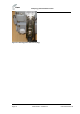
Figure 39 - gland and connector on cable
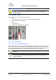
5. Secure the prepared ends of the power cable into the head part of the connector (male
part with visible pins).
Figure 40 - secure cable to connector
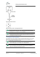
6. Insert and secure the black wire into position 1and the blue wire into position 2.
Figure 41 – power cable wires assembled
Note: Individual connection numbers are marked on each part of the connector.
Figure 42 - numbered connector contacts
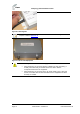
7. Assemble the parts of the connector and tighten the gland to provide a waterproof seal.
Figure 43 - assemble and tighten
8. Prepare the ends of the PSU low voltage cable and thread the connector parts over
the cable.
9. Secure the prepared ends of the drop cable into the head part of the connector (female
part).