
User's Manual


AirSynergy 2000 Installation Guide
Page 37 Commercial in Confidence UGD-D01001 Rev B
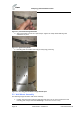
Figure 23 - lift the unit until the bottom studs fit into the bottom slots
Figure 24 - AirSynergy unit engaged into the bottom slots
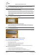
4. Tighten the flange nuts (4 places) to the required degree of down-tilt.
5. Check and tighten all flange nuts.
5.6 Front Mount Antenna Tilt Adjustment
After assembly it is possible to adjust the front mounted antenna tilt-down. There are adjustment
slots located on the sides of unit body and on the sides of the front mounted antenna mounting
plate.
Note: Combined tilt adjustment of both the unit body and the antenna yield a
maximum downtilt of 8°
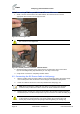
1. Slightly loosen the upper flange nuts (2) where the unit is fixed to the wall/pole mounting
bracket.
Figure 25 - tilt adjustment body
2. Slightly loosen the upper screws (2) where the front mount antenna is fixed to the unit.