
User's Manual


AirSynergy 2000 Installation Guide
Page 56 Commercial in Confidence UGD-D01001 Rev A
10 Appendix B - Field Assembly of Back to Back AirSynergy units
In cases where 2 AirSynergy radios are to be installed on the same mounting bracket some
additional installation steps are required which are as follows:
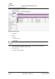
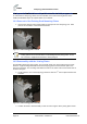
10.1 Removal of the Existing Stud Mounting Plates
1. Remove the existing stud mounting plates (4 places) from each AirSynergy unit. Each
plate is secured with 2 countersunk head screws.
Figure 57 - stud mounting plates removal
Notes: The screws should be replaced with a new set (16 pieces) with new
locking patches on the threads when re-assembling with the joining plates. A new
set of screws is supplied with the back to back joining kit.
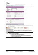
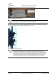
10.2 Reassembly with the Joining Plates
Re-assemble utilizing the joining plates. The studs with flange nuts must all be facing the same
direction. A typical arrangement will be with the AirSynergy with connectorised RF ports to be
mounted at the back. The mounting studs will then all be on the sides of the connectorised unit as
shown in the figure.
2. Fit all 4 plates to one of the AirSynergy units then slide the 2
nd
unit into place between the
brackets.
Figure 58 - stud mounting plates assembly
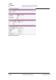
3. Position the back to back assembly on side in order to tighten all the joining plate screws.