
User's Manual


AirSynergy 2000 Installation Guide
Page 37 Commercial in Confidence UGD-D01001 Rev A
No more than 1m between cable termination and first fastener.
Fastenings should be to a robust construction (i.e. mast pole, unit mount…).
Fasteners should be weather and UV resistant.
Cables should have some slack for thermal expansion/contraction between fastenings.
An 25cm, cable connects the GPS directly to the top of AirSynergy. When mounting the GPS
antenna remotely from the unit, the GPS antenna should be used in conjunction with the Remote
GPS Antenna Mounting Bracket (TBD) and appropriate length GPS Cable RG58 TNC-TNC by
way of TNC connectors.
Note: All cables should be properly secured to prevent undue strain on any of
the cable terminations.
Note: AirSynergy units without a factory assembled Switched Beam Antenna all
require a GPS antenna which comes in a kit with a mounting bracket and a 25cm
cable. A primary consideration for a GPS antenna is a clear view of the sky,
preferably 360 degrees.
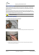
1. Assemble the GPS antenna to the mounting bracket supplied in the GPS antenna
mounting kit. The large black nut should be tightened with a pipe wrench.
Caution: take care not to over tighten the nut so as not to damage the plastic
threads.
Figure 20 - attaching GPS antenna to mounting bracket
2. Attach the short TNC to TNC cable from the GPS antenna to the TNC connecter on the
top of the AirSynergy unit.
Note: For extreme weather conditions weather-proofing of the TNC connections
is recommended. This is done with a layer of self-amalgamating tape followed by
an over layer of PVC tape. The weather-proofing is best done at this stage to give
easier access to the connections.