
User's Manual

Airstream 4001 F49-MRT User Guide
Page 16 Commercial in Confidence UWB-D00211 Rev B
5 Connections
5.1 Power Supply Connector Pinout
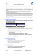
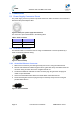
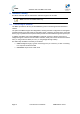
The power supply connector provides 2-pin male contacts for cable connection. The connector is
attached to the power adapter cable.
Figure1‐Powerpins‐powersupplycableconnector
The connector’s pinout is described in the following table:
Table5‐Powerconnector
Power Description
1 “-” power in
2 “+“ power in
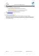
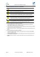
5.2 Ethernet Connection
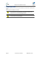
The Ethernet cable is connected to the unit using a standard RJ45 connector protected by a
harsh environment protective casing.
Figure2‐Glandassembly
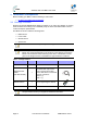
5.2.1 Assemble Ethernet Connector
1. Remove the connector by unscrewing the body from the unit, using the Gland wrench.
2. Pass the Cat 5e Ethernet cable through the tail nut, gland seal, body and rubber seal of the
connector casing as shown above. Do not tighten the tail nut.
3. Terminate the Ethernet cable with an RJ45 connector plug using an RJ45 crimping tool
unless it is pre-assembled.
4. Connect the terminated RJ45 cable to the female RJ45 outlet inside the unit.
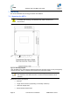
5. Screw the RJ45 gland connector plug securely into the body cavity of the unit using the
provided Gland wrench.
Figure3‐Glandassembled