
User's Manual
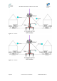
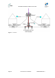
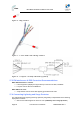
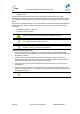
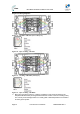
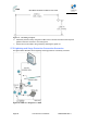

Table Of Contents
- 1.1 Purpose
- 1.4 Referenced Documentation
- 2.1 MicroMAX Frequency Ranges
- 2.2 System Components
- 2.3 Customer Benefits
- 2.4 Architecture
- 2.5 Power
- 2.6 Models
- 3.1 Package Contents
- 3.2 Required Tools
- 3.3 Radio Site Planning
- 4.1 MicroMAX BSR
- 4.2 SDA-4S Type II
- 4.3 SDA-4SDC Type II
- 5.1 Physical Dimensions
- 5.2 Ports
- 6.1 Physical Dimensions
- 6.2 Ports
- 6.3 LEDs
- 6.4 Mounting the GPSD
- 6.5 GPSD Architecture
- 7.1 Physical Dimensions
- 7.2 Ports
- 7.3 Crimping GPS Cable
- 7.4 Contact Socket Crimping
- 8.2 Redundant PS Unit
- 9.1 Pole-Mounting the BSR
- 9.2 Wall-Mounting the BSR (Optional)
- 9.3 Installing the SDA-4S
- 10.1 Desktop mounting
- 10.2 Rack mounting
- 12.1 Rack Mounting
- 12.2 Connecting Redundant PS Unit
- 13.1 Connecting the BSR to the SDA-4S
- 13.2 SDA-4S Type II
- 13.3 Connecting the BSR to BSDU
- 13.4 Connecting BSDU to Network
- 13.5 Connecting BSDUs
- 13.6 Connecting BSDU for SNMP Management
- 14.1 Connecting the SDA-4S Type II
- 14.2 Connecting the SDA-4SDC Type II
- 14.3 Connecting SDA-4S to Ethernet Network
- 15.1 Housing the Connectors
- 15.2 Connecting to the SDA-4SDC
- 16.1 Connections
- 16.2 Power Cable Assembly
- 16.3 Housing the Connectors
- 16.4 Cable Connection
- 17.1 Lightning Protection
- 17.2 Cable Preparation (for grounding)
- 17.3 FM Interference & ESD Protection Recommendations
- 17.4 Connecting Lightning and Surge Protector
- 17.5 Lightning and Surge Protection Connection Scenarios
- 18.1 Connecting GPS Antenna to BSDU
- 19.1 Environmental
- 19.2 Glossary of Terms
- 19.3 Revision History
- 19.4 Contact Information

MicroMAX Hardware Installation User Guide
Page 86 Commercial in Confidence UWB-D00068 Rev J
¾ Deployment of MicroMAX in geographical areas that frequently experience severe
lightning storms
The lightning and surge protector protects the ODU-to-IDU CAT-5e cable's six or eight
(depending on configuration) (for GPS synchronization all 8 CAT-5e wires are used) used wires
(two -48 VDC wires and four Ethernet Tx and Rx wires) from any electrical surges due to lighting
strikes.
The protector is installed outdoors on the CA-5e cable that connects between the MicroMAX and
the SDA-4S Type II (ODU). In other words, two CAT-5e cables are required for the following
connections:
¾ MicroMAX-to-protector connection
¾ Protector-to-IDU connection
Caution: Do not install the lightning and surge protector during adverse
weather conditions when the threat of lightning strike is possible.
Note: The protector unit must be grounded to a low-impedance (low R and
low L) ground system to operate properly.
Note: For pricing and ordering of the Polyphaser lightning and surge
protector, contact your Airspan representative.
To install the lightning protector:
1. Connect the protector in the direction according to the labels. The end labeled SURGE
accepts the cable from the MicroMAX; the end labeled PROTECTED accepts the cable from
the SDA-4S, or BSDU.
2. Feed the CAT-5e cable through the grommet (for each side). If the RJ-45 connector is
already crimped to the other end, ensure that you have fed the cable through the gland nut
beforehand. The gland nut secures the cable to the grommet.
3. Strip about 0.25" (6.35 mm) of the cable sheath and expose about 0.03" (0.8 mm) of the
strands/wires.
4. Secure the wires to the protector's terminal block using the two spot ties. Each side of the
data and DC assembly has + or – markings to ensure lines entering (surge side) match lines
exiting (protected side).
Note: Polyphaser should be installed close to the units but only externally.