
User's Manual
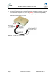
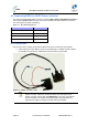
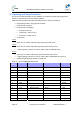
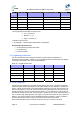
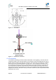
Table Of Contents
- 1.1 Purpose
- 1.4 Referenced Documentation
- 2.1 MicroMAX Frequency Ranges
- 2.2 System Components
- 2.3 Customer Benefits
- 2.4 Architecture
- 2.5 Power
- 2.6 Models
- 3.1 Package Contents
- 3.2 Required Tools
- 3.3 Radio Site Planning
- 4.1 MicroMAX BSR
- 4.2 SDA-4S Type II
- 4.3 SDA-4SDC Type II
- 5.1 Physical Dimensions
- 5.2 Ports
- 6.1 Physical Dimensions
- 6.2 Ports
- 6.3 LEDs
- 6.4 Mounting the GPSD
- 6.5 GPSD Architecture
- 7.1 Physical Dimensions
- 7.2 Ports
- 7.3 Crimping GPS Cable
- 7.4 Contact Socket Crimping
- 8.2 Redundant PS Unit
- 9.1 Pole-Mounting the BSR
- 9.2 Wall-Mounting the BSR (Optional)
- 9.3 Installing the SDA-4S
- 10.1 Desktop mounting
- 10.2 Rack mounting
- 12.1 Rack Mounting
- 12.2 Connecting Redundant PS Unit
- 13.1 Connecting the BSR to the SDA-4S
- 13.2 SDA-4S Type II
- 13.3 Connecting the BSR to BSDU
- 13.4 Connecting BSDU to Network
- 13.5 Connecting BSDUs
- 13.6 Connecting BSDU for SNMP Management
- 14.1 Connecting the SDA-4S Type II
- 14.2 Connecting the SDA-4SDC Type II
- 14.3 Connecting SDA-4S to Ethernet Network
- 15.1 Housing the Connectors
- 15.2 Connecting to the SDA-4SDC
- 16.1 Connections
- 16.2 Power Cable Assembly
- 16.3 Housing the Connectors
- 16.4 Cable Connection
- 17.1 Lightning Protection
- 17.2 Cable Preparation (for grounding)
- 17.3 FM Interference & ESD Protection Recommendations
- 17.4 Connecting Lightning and Surge Protector
- 17.5 Lightning and Surge Protection Connection Scenarios
- 18.1 Connecting GPS Antenna to BSDU
- 19.1 Environmental
- 19.2 Glossary of Terms
- 19.3 Revision History
- 19.4 Contact Information

MicroMAX Hardware Installation User Guide
Page 79 Commercial in Confidence UWB-D00068 Rev J
Level of
Protection
Flash density * Equipment placement
**
Installation accessibility
***
Landscape
3 High - - Hilly
2 Low - Good Mountainous
3 Low - Poor Mountainous
3 Medium - - Mountainous
3 High - - Mountainous
* Density (strikes per kilometer square per year)
o Low = Less than 5
o Medium = 5 – 14
o High = more than 14
** Relative to ground level
*** Accessibility – cost/time affects replacement considerations
Recommended good practices:
¾ Air-terminal and grounded mast/tower.
¾ Proper Bonding
¾ Proper Grounding
17.1 Lightning Protection
This is to describe the known mitigation defenses in general terms for application to
telecommunications facilities. A hierarchy of recognized application methods should be applied
according to site realities. This matrix is depicted below:
Table 28 - Application matrix
Exterior locationInterior LocationPeople SafetyStructure Safety
Air Terminals Yes No No Yes
Down Conductors Yes Yes No Yes
Bonding Yes Yes Yes Yes
Grounding Yes Yes Yes Yes
Surge Protection Yes Yes Yes Yes
17.1.1 Air Terminals
Lightning usually terminates on grounded objects sticking up in the air. This part of a lightning
protection system (LPS) is based upon the principles of Path of Least Impedance. On telecom
towers, ordinary sacrificial rods can protect sensitive antennae. In the main, the tower is the air
terminal. the height (“H”) of the Air Terminal tip above the highest element on the tower or pole,
typically the antenna, must be at least twice the distance (“2 x d”) between the outer surface of
the antenna and the tower or pole. This will ensure a "protection cone" of 45º around the tower or
pole. In areas of high lightning activity, the length (“H”) should be increased to up to 5 times the
distance. The Down Conductor must be installed straight and vertically in order to provide the
shortest and most direct path to earth. The formation of bends must be avoided.
We recommend that the Down-Conductor be at least 50 mm2 or AWG 0 in all cases.