
User's Manual
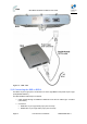
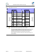

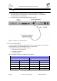
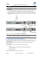
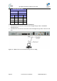

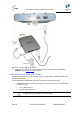

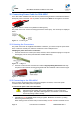
Table Of Contents
- 1.1 Purpose
- 1.4 Referenced Documentation
- 2.1 MicroMAX Frequency Ranges
- 2.2 System Components
- 2.3 Customer Benefits
- 2.4 Architecture
- 2.5 Power
- 2.6 Models
- 3.1 Package Contents
- 3.2 Required Tools
- 3.3 Radio Site Planning
- 4.1 MicroMAX BSR
- 4.2 SDA-4S Type II
- 4.3 SDA-4SDC Type II
- 5.1 Physical Dimensions
- 5.2 Ports
- 6.1 Physical Dimensions
- 6.2 Ports
- 6.3 LEDs
- 6.4 Mounting the GPSD
- 6.5 GPSD Architecture
- 7.1 Physical Dimensions
- 7.2 Ports
- 7.3 Crimping GPS Cable
- 7.4 Contact Socket Crimping
- 8.2 Redundant PS Unit
- 9.1 Pole-Mounting the BSR
- 9.2 Wall-Mounting the BSR (Optional)
- 9.3 Installing the SDA-4S
- 10.1 Desktop mounting
- 10.2 Rack mounting
- 12.1 Rack Mounting
- 12.2 Connecting Redundant PS Unit
- 13.1 Connecting the BSR to the SDA-4S
- 13.2 SDA-4S Type II
- 13.3 Connecting the BSR to BSDU
- 13.4 Connecting BSDU to Network
- 13.5 Connecting BSDUs
- 13.6 Connecting BSDU for SNMP Management
- 14.1 Connecting the SDA-4S Type II
- 14.2 Connecting the SDA-4SDC Type II
- 14.3 Connecting SDA-4S to Ethernet Network
- 15.1 Housing the Connectors
- 15.2 Connecting to the SDA-4SDC
- 16.1 Connections
- 16.2 Power Cable Assembly
- 16.3 Housing the Connectors
- 16.4 Cable Connection
- 17.1 Lightning Protection
- 17.2 Cable Preparation (for grounding)
- 17.3 FM Interference & ESD Protection Recommendations
- 17.4 Connecting Lightning and Surge Protector
- 17.5 Lightning and Surge Protection Connection Scenarios
- 18.1 Connecting GPS Antenna to BSDU
- 19.1 Environmental
- 19.2 Glossary of Terms
- 19.3 Revision History
- 19.4 Contact Information

MicroMAX Hardware Installation User Guide
Page 65 Commercial in Confidence UWB-D00068 Rev J
Note: Pins not defined are not used.
To chain BSDUs:
1. On the first BSDU, connect the RJ-45 connector, at one end of the crossover cable, to one of
the two 10/100/1000 Base-T ports (labeled 1 or 2) located on the BSDU's front panel.
2. On the second BSDU, connect the RJ-45 connector, at the other end of the crossover cable,
to one of the two BSDU's 10/100/1000 Base-T ports (labeled 1 or 2) located on the BSDU's
front panel.
Figure 47 - Cable connections for BSDU chaining with GPS
Note: When connecting BSDU's it does not matter which one of the two
10/100/1000 Base-T ports you use two connect two BSDUs.
13.6 Connecting BSDU for SNMP Management
To configure the BSDU, or BSRs connected to the BSDU, through an IP network communication
mode, you can connect the BSDU directly to the PC, or remotely (from anywhere) if you have IP
connectivity to the PC.
For PC-to-BSDU local network connections you need to connect the PC to the BSDU's
management port.
The following lists the cable setup for BSDU local network management:
¾ Cables:
• Straight-through for connecting the PC to the BSDU management port
¾ Connector: 8-pin RJ-45
¾ Connector pinouts:
Table 25 - BSDU to PC for IP network management