
User's Manual
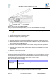
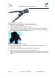
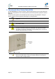
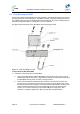
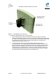
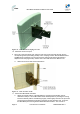
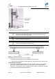
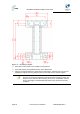
Table Of Contents
- 1.1 Purpose
- 1.4 Referenced Documentation
- 2.1 MicroMAX Frequency Ranges
- 2.2 System Components
- 2.3 Customer Benefits
- 2.4 Architecture
- 2.5 Power
- 2.6 Models
- 3.1 Package Contents
- 3.2 Required Tools
- 3.3 Radio Site Planning
- 4.1 MicroMAX BSR
- 4.2 SDA-4S Type II
- 4.3 SDA-4SDC Type II
- 5.1 Physical Dimensions
- 5.2 Ports
- 6.1 Physical Dimensions
- 6.2 Ports
- 6.3 LEDs
- 6.4 Mounting the GPSD
- 6.5 GPSD Architecture
- 7.1 Physical Dimensions
- 7.2 Ports
- 7.3 Crimping GPS Cable
- 7.4 Contact Socket Crimping
- 8.2 Redundant PS Unit
- 9.1 Pole-Mounting the BSR
- 9.2 Wall-Mounting the BSR (Optional)
- 9.3 Installing the SDA-4S
- 10.1 Desktop mounting
- 10.2 Rack mounting
- 12.1 Rack Mounting
- 12.2 Connecting Redundant PS Unit
- 13.1 Connecting the BSR to the SDA-4S
- 13.2 SDA-4S Type II
- 13.3 Connecting the BSR to BSDU
- 13.4 Connecting BSDU to Network
- 13.5 Connecting BSDUs
- 13.6 Connecting BSDU for SNMP Management
- 14.1 Connecting the SDA-4S Type II
- 14.2 Connecting the SDA-4SDC Type II
- 14.3 Connecting SDA-4S to Ethernet Network
- 15.1 Housing the Connectors
- 15.2 Connecting to the SDA-4SDC
- 16.1 Connections
- 16.2 Power Cable Assembly
- 16.3 Housing the Connectors
- 16.4 Cable Connection
- 17.1 Lightning Protection
- 17.2 Cable Preparation (for grounding)
- 17.3 FM Interference & ESD Protection Recommendations
- 17.4 Connecting Lightning and Surge Protector
- 17.5 Lightning and Surge Protection Connection Scenarios
- 18.1 Connecting GPS Antenna to BSDU
- 19.1 Environmental
- 19.2 Glossary of Terms
- 19.3 Revision History
- 19.4 Contact Information

MicroMAX Hardware Installation User Guide
Page 49 Commercial in Confidence UWB-D00068 Rev J
Figure 32 - strain relief
9.2 Wall-Mounting the BSR (Optional)
Note: The standard BSR kit provides pole-mounting brackets. If you want to
wall-mount the MicroMAX BSR contact your Airspan distributor for pricing
and ordering of wall-mounting brackets.
Note: A minimum of 3 meter separation is required between MicroMAX and
existing customer radio equipment.
Note: A minimum of 1 meter separation should be maintained between
synchronized MicroMAXs (see figure below).
The figure below illustrates the minimum separation between synchronized MicroMAX's :
Figure 33 - mount separation
MicroMAX wall mounting consists of two main stages:
¾ Attaching the mounting bracket to the MicroMAX's mounting holes
¾ Attaching the mounting bracket (already attached to the MicroMAX) to the wall (or pole)
To wall mount the MicroMAX:
1. Position the unassembled mounting bracket on the mounting surface (e.g. wall), and then
use a pencil to mark the position of the four mounting holes. Ensure that the distance
between the hole centers are 120 mm (height) and 60 mm (width), as displayed in the figure
below showing the MicroMAX's fixing dimensions.