
User's Manual
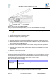
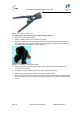
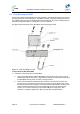
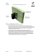
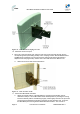
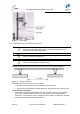
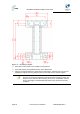
Table Of Contents
- 1.1 Purpose
- 1.4 Referenced Documentation
- 2.1 MicroMAX Frequency Ranges
- 2.2 System Components
- 2.3 Customer Benefits
- 2.4 Architecture
- 2.5 Power
- 2.6 Models
- 3.1 Package Contents
- 3.2 Required Tools
- 3.3 Radio Site Planning
- 4.1 MicroMAX BSR
- 4.2 SDA-4S Type II
- 4.3 SDA-4SDC Type II
- 5.1 Physical Dimensions
- 5.2 Ports
- 6.1 Physical Dimensions
- 6.2 Ports
- 6.3 LEDs
- 6.4 Mounting the GPSD
- 6.5 GPSD Architecture
- 7.1 Physical Dimensions
- 7.2 Ports
- 7.3 Crimping GPS Cable
- 7.4 Contact Socket Crimping
- 8.2 Redundant PS Unit
- 9.1 Pole-Mounting the BSR
- 9.2 Wall-Mounting the BSR (Optional)
- 9.3 Installing the SDA-4S
- 10.1 Desktop mounting
- 10.2 Rack mounting
- 12.1 Rack Mounting
- 12.2 Connecting Redundant PS Unit
- 13.1 Connecting the BSR to the SDA-4S
- 13.2 SDA-4S Type II
- 13.3 Connecting the BSR to BSDU
- 13.4 Connecting BSDU to Network
- 13.5 Connecting BSDUs
- 13.6 Connecting BSDU for SNMP Management
- 14.1 Connecting the SDA-4S Type II
- 14.2 Connecting the SDA-4SDC Type II
- 14.3 Connecting SDA-4S to Ethernet Network
- 15.1 Housing the Connectors
- 15.2 Connecting to the SDA-4SDC
- 16.1 Connections
- 16.2 Power Cable Assembly
- 16.3 Housing the Connectors
- 16.4 Cable Connection
- 17.1 Lightning Protection
- 17.2 Cable Preparation (for grounding)
- 17.3 FM Interference & ESD Protection Recommendations
- 17.4 Connecting Lightning and Surge Protector
- 17.5 Lightning and Surge Protection Connection Scenarios
- 18.1 Connecting GPS Antenna to BSDU
- 19.1 Environmental
- 19.2 Glossary of Terms
- 19.3 Revision History
- 19.4 Contact Information

MicroMAX Hardware Installation User Guide
Page 45 Commercial in Confidence UWB-D00068 Rev J
9.1 Pole-Mounting the BSR
Pole mounting allows the MicroMAX to be easily adjusted in the horizontal (azimuth) and vertical
(elevation) planes for antenna alignment. The BSR is mounted using the mounting holes located
on the BSR's back panel and the supplied pole-mounting brackets. The pole-mounting bracket is
designed to support the BSR on a round pole of 45 mm in diameter.
The figure below summarizes of the MicroMAX's pole-mounting procedure.
Figure 26 - Pole mounting bracket
To pole mount the MicroMAX BSR:
8. Attach the mounting bracket to the MicroMAX:
a. Align the mounting bracket with the MicroMAX's mounting holes so that the mounting
bracket's side with the built-in nut is aligned with the BSR's mounting holes furthest from
the MicroMAX's bottom panel, as shown in the figure below.
b. Slide an M10-flat washer and M10-spring lock washer onto an M10-hex head screw
(ensure spring lock washer is closest to the bolt's head). From the external side, insert
the M10-hex head screw through the mounting bracket and MicroMAX's mounting holes.
Fasten the M10-hex head screw (one is provided with a built-in nut while the other
requires you to insert an M10-hex nut into the MicroMAX's mounting hole). After
alignment is completed, tighten bolts. Max torgue for M10 is 44Nm (32lbf.ft.).