
User's Manual
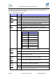
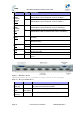

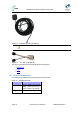
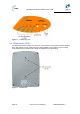
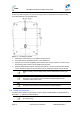
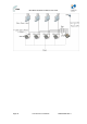
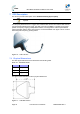
Table Of Contents
- 1.1 Purpose
- 1.4 Referenced Documentation
- 2.1 MicroMAX Frequency Ranges
- 2.2 System Components
- 2.3 Customer Benefits
- 2.4 Architecture
- 2.5 Power
- 2.6 Models
- 3.1 Package Contents
- 3.2 Required Tools
- 3.3 Radio Site Planning
- 4.1 MicroMAX BSR
- 4.2 SDA-4S Type II
- 4.3 SDA-4SDC Type II
- 5.1 Physical Dimensions
- 5.2 Ports
- 6.1 Physical Dimensions
- 6.2 Ports
- 6.3 LEDs
- 6.4 Mounting the GPSD
- 6.5 GPSD Architecture
- 7.1 Physical Dimensions
- 7.2 Ports
- 7.3 Crimping GPS Cable
- 7.4 Contact Socket Crimping
- 8.2 Redundant PS Unit
- 9.1 Pole-Mounting the BSR
- 9.2 Wall-Mounting the BSR (Optional)
- 9.3 Installing the SDA-4S
- 10.1 Desktop mounting
- 10.2 Rack mounting
- 12.1 Rack Mounting
- 12.2 Connecting Redundant PS Unit
- 13.1 Connecting the BSR to the SDA-4S
- 13.2 SDA-4S Type II
- 13.3 Connecting the BSR to BSDU
- 13.4 Connecting BSDU to Network
- 13.5 Connecting BSDUs
- 13.6 Connecting BSDU for SNMP Management
- 14.1 Connecting the SDA-4S Type II
- 14.2 Connecting the SDA-4SDC Type II
- 14.3 Connecting SDA-4S to Ethernet Network
- 15.1 Housing the Connectors
- 15.2 Connecting to the SDA-4SDC
- 16.1 Connections
- 16.2 Power Cable Assembly
- 16.3 Housing the Connectors
- 16.4 Cable Connection
- 17.1 Lightning Protection
- 17.2 Cable Preparation (for grounding)
- 17.3 FM Interference & ESD Protection Recommendations
- 17.4 Connecting Lightning and Surge Protector
- 17.5 Lightning and Surge Protection Connection Scenarios
- 18.1 Connecting GPS Antenna to BSDU
- 19.1 Environmental
- 19.2 Glossary of Terms
- 19.3 Revision History
- 19.4 Contact Information

MicroMAX Hardware Installation User Guide
Page 33 Commercial in Confidence UWB-D00068 Rev J
6 GPSD Description
This section provides a description of the Global Positioning System Distribution unit (GPSD)
(Optional). The GPSD distributes GPS synchronization to up to 4 BSRs.
The GPSD unit is a, self-contained GPS Distribution unit and is available in 2 models, either in 10
to 52 VDC or in 110-240 VAC, 1A, 50/60 Hz, 50W. The GPSD is an optional unit that connects up
to four (4) SDA-4S (or SDA-4SDCs).
Table 14 - GPSD Voltage & Currency Ratings
Models Ratings
AC 110-240 VAC, 0.25A
DC 10-52 VDC, 1A
Note: The DC unit should be powered by a limited power source of up to 3A.
The GPSD incorporates two (2) connections for different GPS connections. There is an SMA
connection for use with the included external GPS antenna which works in conjunction with the
internal GPS module. The internal GPS synchronizes multiple (up to 4) Base Stations, ensuring
that the entire network operates with the same clock based on a universal satellite clock signal.
There is also a 15-PIN D-Type connection for use with a third-party GPS antenna. The GPSD,
external antenna and “Y” cable are displayed in the figures below:
Figure 10 – GPSD
Note: Service personnel must install the AC unit connected to a properly
grounded outlet.
Note: To reduce the risk of fire only no.26 AWG or larger telecommunication
line cord should be used.