
User's Manual
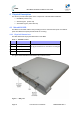
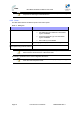
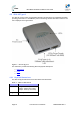
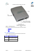
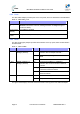
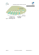
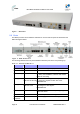
Table Of Contents
- 1.1 Purpose
- 1.4 Referenced Documentation
- 2.1 MicroMAX Frequency Ranges
- 2.2 System Components
- 2.3 Customer Benefits
- 2.4 Architecture
- 2.5 Power
- 2.6 Models
- 3.1 Package Contents
- 3.2 Required Tools
- 3.3 Radio Site Planning
- 4.1 MicroMAX BSR
- 4.2 SDA-4S Type II
- 4.3 SDA-4SDC Type II
- 5.1 Physical Dimensions
- 5.2 Ports
- 6.1 Physical Dimensions
- 6.2 Ports
- 6.3 LEDs
- 6.4 Mounting the GPSD
- 6.5 GPSD Architecture
- 7.1 Physical Dimensions
- 7.2 Ports
- 7.3 Crimping GPS Cable
- 7.4 Contact Socket Crimping
- 8.2 Redundant PS Unit
- 9.1 Pole-Mounting the BSR
- 9.2 Wall-Mounting the BSR (Optional)
- 9.3 Installing the SDA-4S
- 10.1 Desktop mounting
- 10.2 Rack mounting
- 12.1 Rack Mounting
- 12.2 Connecting Redundant PS Unit
- 13.1 Connecting the BSR to the SDA-4S
- 13.2 SDA-4S Type II
- 13.3 Connecting the BSR to BSDU
- 13.4 Connecting BSDU to Network
- 13.5 Connecting BSDUs
- 13.6 Connecting BSDU for SNMP Management
- 14.1 Connecting the SDA-4S Type II
- 14.2 Connecting the SDA-4SDC Type II
- 14.3 Connecting SDA-4S to Ethernet Network
- 15.1 Housing the Connectors
- 15.2 Connecting to the SDA-4SDC
- 16.1 Connections
- 16.2 Power Cable Assembly
- 16.3 Housing the Connectors
- 16.4 Cable Connection
- 17.1 Lightning Protection
- 17.2 Cable Preparation (for grounding)
- 17.3 FM Interference & ESD Protection Recommendations
- 17.4 Connecting Lightning and Surge Protector
- 17.5 Lightning and Surge Protection Connection Scenarios
- 18.1 Connecting GPS Antenna to BSDU
- 19.1 Environmental
- 19.2 Glossary of Terms
- 19.3 Revision History
- 19.4 Contact Information

MicroMAX Hardware Installation User Guide
Page 30 Commercial in Confidence UWB-D00068 Rev J
Figure 7 - BSDU front
5.2 Ports
The BSDU provides various hardware interfaces on its front and rear panel as described in the
tables and figures below.
Figure 8 - BSDU Front Panel
The following table lists the front panel hardware interfaces (refer to the front panel figure):
Table 11 - Front Panel Interfaces
Port Label Interface
8-pin RJ-45 (4) 10/100 4 x 10/100 BaseT general purpose switch
8-pin RJ-45 MNG 10/100 BaseT for out-of-band management
8-pin RJ-45 (2) 10/100/1000 1 / 2 1 - Interface with provider’s backbone
2 – Daisy-chained BSDUs, interface with another
BSDU for cascading
SMA (2) GPS
10MHz IN & 1PPS IN
Interface with GPS for global clock synchronization
by means of 2 signals: 10 MHz and 1 PPS
For future use
SMA (2) CASCADE
10MHz & 1PPS
Interfaces with a daisy-chained BSDU for
cascading the 2 GPS signals
For future use
8-pin RJ-45 GPS COM Interfaces with the GPS serial port for getting
status and alarms
8-pin RJ-45 CONSOLE BSDU serial port for initial configuration
Power
Receptacle
-48VDC -48 VDC supply from external feeding source