
User Manual
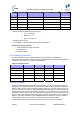
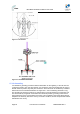
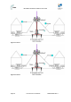
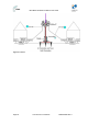
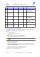
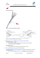
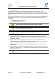
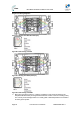
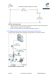
Table Of Contents
- 1 About this Guide
- 2 System Overview
- 3 Installation Prerequisites
- 4 Physical Description
- 5 BSDU Description
- 6 GPSD Description
- 7 GPS Description
- 8 AC/DC Power Converter
- 9 Mounting the Base Station Radio (BSR)
- 10 Mounting the BSDU
- 11 Mounting the GPS
- 12 Mounting the AC/DC Power Converter
- 13 Cabling the BSR
- 14 Connecting the SDA-4S to the power supply
- 15 Connecting Power Cable for SDA-4SDC
- 16 Connecting BSDU to AC/DC Power converter
- 17 Lightning and Surge Protection
- 18 Connecting Third-Party External Antennas
- 19 Appendix

MicroMAX Hardware Installation User Guide
Page 86 Commercial in Confidence UWB-D00068 Rev J
Table31–Accessories
Item
No.
Description Manufacturer Manufacturer
P/N
QuantityRemark
1
Copperwire0AWG
N/A
N/A N/A Groundresistancemustbe
lessthan1Ohm.
ULapprovedcable
2
CAT‐5eSFTPwith
drainanddouble
jacket
N/A
N/A N/A Upto100meters
3
BareCopperWire4/0
AWG
N/A
N/A N/A Groundresistancemustbe
lessthan5Ohm.
ULapprovedcable
Ringterminal
N/A
N/A N/A StudH(1/4),Diameter
matchingtheusedCopper
Wirediameter.
CircuitLightning
protectionforBSR
PolyphaserIX
series
IX‐2H1L1DC48‐
IG
1
InstalledwithBSR
CircuitLightning
protectionforProST
PolyphaserIX
series
IX‐2H1DC48‐IG
1
InstalledwithProST
17.2 Cable Preparation (for grounding)
The CAT-5e SFTP cable is supplied unassembled. Therefore, you need to crimp the drain wire to
the ring terminal and paired wires to the connector's contact pins.
Required:
¾ CAT-5e SFTP cable
¾ Ring terminal and red insulation boot
¾ Crimping tool
To crimp the CAT-5e SFTP “drain” wire to the ring terminal:
1. Carefully strip the insulation from the SFTP cable (5 – 10cm).
Caution: Do not damage the insulation of the inner twisted pair wires.
2. Peel back the foil from around the wires.
3. Isolate the “drain” (ground) wire.
4. Crimp the ring terminal to the drain wire. Insert the wire into the ring terminal’s barrel, and
then, with a standard crimping tool crimp the barrel tightly onto the wire. Fold back the drain
wire with the ring terminal attached.
5. Strip the ends of the paired wires according to the connector.
6. Connect ground wire (with extension if required) to the tower.
The figures and connections are displayed below: