
User Manual
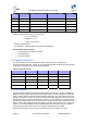
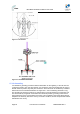
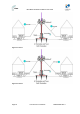
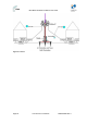
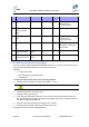
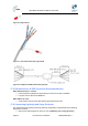
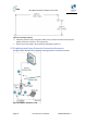
Table Of Contents
- 1 About this Guide
- 2 System Overview
- 3 Installation Prerequisites
- 4 Physical Description
- 5 BSDU Description
- 6 GPSD Description
- 7 GPS Description
- 8 AC/DC Power Converter
- 9 Mounting the Base Station Radio (BSR)
- 10 Mounting the BSDU
- 11 Mounting the GPS
- 12 Mounting the AC/DC Power Converter
- 13 Cabling the BSR
- 14 Connecting the SDA-4S to the power supply
- 15 Connecting Power Cable for SDA-4SDC
- 16 Connecting BSDU to AC/DC Power converter
- 17 Lightning and Surge Protection
- 18 Connecting Third-Party External Antennas
- 19 Appendix

MicroMAX Hardware Installation User Guide
Page 81 Commercial in Confidence UWB-D00068 Rev J
Level of
Protection
Flash density * Equipment placement
**
Installation accessibility
***
Landscape
3 High - - Hilly
2 Low - Good Mountainous
3 Low - Poor Mountainous
3 Medium - - Mountainous
3 High - - Mountainous
* Density (strikes per kilometer square per year)
o Low = Less than 5
o Medium = 5 – 14
o High = more than 14
** Relative to ground level
*** Accessibility – cost/time affects replacement considerations
Recommended good practices:
¾ Air-terminal and grounded mast/tower.
¾ Proper Bonding
¾ Proper Grounding
17.1 Lightning Protection
This is to describe the known mitigation defenses in general terms for application to
telecommunications facilities. A hierarchy of recognized application methods should be applied
according to site realities. This matrix is depicted below:
Table30‐Applicationmatrix
Exterior locationInterior LocationPeople SafetyStructure Safety
Air Terminals Yes No No Yes
Down Conductors Yes Yes No Yes
Bonding Yes Yes Yes Yes
Grounding Yes Yes Yes Yes
Surge Protection Yes Yes Yes Yes
17.1.1 Air Terminals
Lightning usually terminates on grounded objects sticking up in the air. This part of a lightning
protection system (LPS) is based upon the principles of Path of Least Impedance. On telecom
towers, ordinary sacrificial rods can protect sensitive antennae. In the main, the tower is the air
terminal. the height (“H”) of the Air Terminal tip above the highest element on the tower or pole,
typically the antenna, must be at least twice the distance (“2 x d”) between the outer surface of
the antenna and the tower or pole. This will ensure a "protection cone" of 45º around the tower or
pole. In areas of high lightning activity, the length (“H”) should be increased to up to 5 times the
distance. The Down Conductor must be installed straight and vertically in order to provide the
shortest and most direct path to earth. The formation of bends must be avoided.
We recommend that the Down-Conductor be at least 50 mm2 or AWG 0 in all cases.