
User Manual
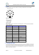
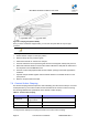
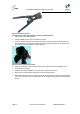
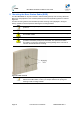
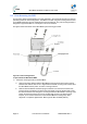
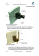
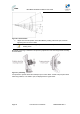
Table Of Contents
- 1 About this Guide
- 2 System Overview
- 3 Installation Prerequisites
- 4 Physical Description
- 5 BSDU Description
- 6 GPSD Description
- 7 GPS Description
- 8 AC/DC Power Converter
- 9 Mounting the Base Station Radio (BSR)
- 10 Mounting the BSDU
- 11 Mounting the GPS
- 12 Mounting the AC/DC Power Converter
- 13 Cabling the BSR
- 14 Connecting the SDA-4S to the power supply
- 15 Connecting Power Cable for SDA-4SDC
- 16 Connecting BSDU to AC/DC Power converter
- 17 Lightning and Surge Protection
- 18 Connecting Third-Party External Antennas
- 19 Appendix

MicroMAX Hardware Installation User Guide
Page 42 Commercial in Confidence UWB-D00068 Rev J
7.2 Ports
The GPS provides 12-pin male contacts for connecting a cable between it and the BSDU.
Figure18‐GPSpinouts
Figure19‐Db‐15
The connectors’ pinouts are described in the following table; connections should be as defined.
Table21‐GPSPinouts
Db-15 Connector GPS connector Description (GPS side)
13 1 Power +
6 2 Receive -
5 3 Receive +
4 4 Transmit –
3 5 Transmit +
-- 6(NC)
-- 7(NC)
-- 8(NC)
12 9 Power -
10(NC)
7 11 PPS+
8 12 PPS-
7.3 Crimping GPS Cable
The third-party Global Positioning System antenna (GPS) connects to the BSDU's 15-pin D-type
port. Therefore, the cable from the GPS needs to be crimped to a 15-pin D-type male connector.
Airspan recommends using the Daniels AFM8 (M22520/2-01) crimping tool for crimping the GPS
cable to 15-pin D-type connectors.