
User Manual
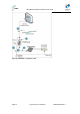
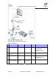
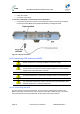

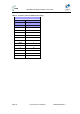
Table Of Contents
- 1 About this Guide
- 2 System Overview
- 3 Installation Prerequisites
- 4 Physical Description
- 5 BSDU Description
- 6 GPSD Description
- 7 GPS Description
- 8 AC/DC Power Converter
- 9 Mounting the Base Station Radio (BSR)
- 10 Mounting the BSDU
- 11 Mounting the GPS
- 12 Mounting the AC/DC Power Converter
- 13 Cabling the BSR
- 14 Connecting the SDA-4S to the power supply
- 15 Connecting Power Cable for SDA-4SDC
- 16 Connecting BSDU to AC/DC Power converter
- 17 Lightning and Surge Protection
- 18 Connecting Third-Party External Antennas
- 19 Appendix

MicroMAX Hardware Installation User Guide
Page 96 Commercial in Confidence UWB-D00068 Rev J
The connector pinouts for the GPS-to-BSDU 12-pin cabling are described in the table below.
Table33‐ConnectorpinoutsforBSDU‐to‐GPScabling
Multipair overall shielded (22 AWG) cable
GPS BSDU
12-pin female 15-pin D-type male
Pin Pin
1 13
2 6
3 5
4 4
5 3
6(NC) x
7(NC) x
8(NC) x
9 12
10 x
11 7
12 8