
User Manual
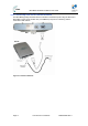
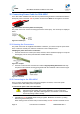
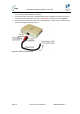
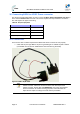
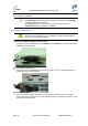
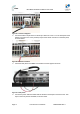
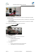
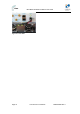
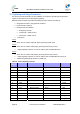
Table Of Contents
- 1 About this Guide
- 2 System Overview
- 3 Installation Prerequisites
- 4 Physical Description
- 5 BSDU Description
- 6 GPSD Description
- 7 GPS Description
- 8 AC/DC Power Converter
- 9 Mounting the Base Station Radio (BSR)
- 10 Mounting the BSDU
- 11 Mounting the GPS
- 12 Mounting the AC/DC Power Converter
- 13 Cabling the BSR
- 14 Connecting the SDA-4S to the power supply
- 15 Connecting Power Cable for SDA-4SDC
- 16 Connecting BSDU to AC/DC Power converter
- 17 Lightning and Surge Protection
- 18 Connecting Third-Party External Antennas
- 19 Appendix

MicroMAX Hardware Installation User Guide
Page 78 Commercial in Confidence UWB-D00068 Rev J
Figure68‐Frontpowerconnect
7. Connect the opposite ends of the cable to the DC output on the Rear Panel of the AC/DC
Convertor as follows:
a. The +VDC (Positive) output of the AC/DC converter is connected to the + Positive (Red)
input on the BSDU
b. The -VDC (NEGATIVE) output of the AC/DC converter is connected to the - Negative
(Black) input on the BSDU
The rear panels of the BSDU and AC/DC converter, shown below:
Figure69‐Rearpanels
8. Connect the AC/DC converter to AC Power and verify that:
a. On the AC/DC converter:
i. DC Supply module fans start up
ii. Green AC OK LED is lit
iii. DC OK LED is lit
b. On the BSDU:
i. All LEDs on the front panel are lit for several seconds
ii. The POWER LED on the front panel remains lit