
User Manual
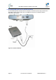
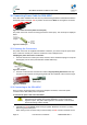
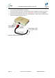
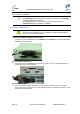
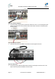
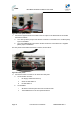
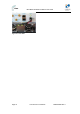
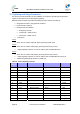
Table Of Contents
- 1 About this Guide
- 2 System Overview
- 3 Installation Prerequisites
- 4 Physical Description
- 5 BSDU Description
- 6 GPSD Description
- 7 GPS Description
- 8 AC/DC Power Converter
- 9 Mounting the Base Station Radio (BSR)
- 10 Mounting the BSDU
- 11 Mounting the GPS
- 12 Mounting the AC/DC Power Converter
- 13 Cabling the BSR
- 14 Connecting the SDA-4S to the power supply
- 15 Connecting Power Cable for SDA-4SDC
- 16 Connecting BSDU to AC/DC Power converter
- 17 Lightning and Surge Protection
- 18 Connecting Third-Party External Antennas
- 19 Appendix

MicroMAX Hardware Installation User Guide
Page 76 Commercial in Confidence UWB-D00068 Rev J
This cable connects between the rear panel of the AC/DC Converter and the -48V Power Input on
the Front Panel of the BSDU.
Note: Ensure that:
The POSITIVE output of the AC/DC Converter is connected to the POSITIVE
(Red) input (lower) on the BSDU.
The NEGATIVE output of the AC/DC Converter is connected to the
NEGATIVE (Black) input (upper) on the BSDU.
16.4 Cable Connection
Caution: Confirm that all inputs to the AC/DC converter are either
disconnected or powered off prior to installing the cable, otherwise damage
may occur to either or both devices.
To connect the BSDU to AC/DC Converter Cable
1. Connect the end of cable 63000110 labeled BSDU to the PS MNG port on the back panel of
the BSDU, as shown below.
Figure63‐BSDUtoPSMNGport
2. Connect the end of cable 63000110 marked ‘PSU’ to the ‘J1’ port on the back panel of the
AC/DC Convertor, as shown below.
Figure64‐PSUtoJ1port
3. Connect the Black crimped wire from the 25-pin cable connected to Port J1 on the back
panel of the AC/DC Convertor to the –VDC (Negative) output of the AC/DC Convertor on the
back panel, as shown below.