
User Manual
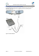
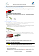
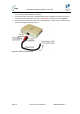
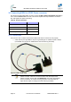
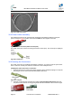
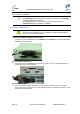
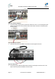
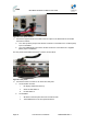
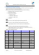
Table Of Contents
- 1 About this Guide
- 2 System Overview
- 3 Installation Prerequisites
- 4 Physical Description
- 5 BSDU Description
- 6 GPSD Description
- 7 GPS Description
- 8 AC/DC Power Converter
- 9 Mounting the Base Station Radio (BSR)
- 10 Mounting the BSDU
- 11 Mounting the GPS
- 12 Mounting the AC/DC Power Converter
- 13 Cabling the BSR
- 14 Connecting the SDA-4S to the power supply
- 15 Connecting Power Cable for SDA-4SDC
- 16 Connecting BSDU to AC/DC Power converter
- 17 Lightning and Surge Protection
- 18 Connecting Third-Party External Antennas
- 19 Appendix

MicroMAX Hardware Installation User Guide
Page 72 Commercial in Confidence UWB-D00068 Rev J
15 Connecting Power Cable for SDA-4SDC
In the SDA-4SDC installation Kit there are two polarized and genderless unassembled Anderson
Powerpole power connectors: red for positive connection and black for the negative connection.
Figure52‐Powerconnectors(AndersonPowerpole)
The power connectors consist of housing (hood and a contact pins). The contact pin is displayed
below:
Figure53‐Contactpin
15.1 Housing the Connectors
The power connectors are supplied unassembled. Therefore, you need to crimp the power wires
to the connector's contact pins, and then house them in the Powerpole hood.
Crimping the power wires to the connectors:
1. Insert the wire into the contact pin's barrel, and then, with a standard crimping tool crimp the
barrel tightly onto the wire (recommended 16 AWG cable wire).
Figure54–crimped
2. Insert the contact into the hood with the contact's tongue pointing downwards and snap
into place. Ensure that the housing spring mates with the underside of the contact's tongue.
Figure55–Insertion
15.2 Connecting to the SDA-4SDC
Once you have crimped the power cord to the Powerpole connectors, connect the power
connectors to the SDA-4SDC power receptacles.
To connect the power cord to the SDA-4SDC:
Caution: The plastic housings are held together with dovetail joints. Always
slide these joints together! They will be damaged if you try to snap them
together or apart. They ONLY slide together in one direction. This should be
obvious by looking at them carefully.
1. Assemble the red and black plastic housings together. Mate both connectors, by sliding
them along the dovetail joints.
When looking at the connector side (not the wire side), the red connector should be on the