
User Manual
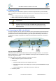
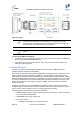

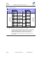
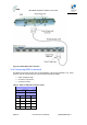
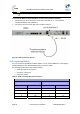

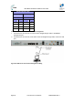

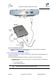
Table Of Contents
- 1 About this Guide
- 2 System Overview
- 3 Installation Prerequisites
- 4 Physical Description
- 5 BSDU Description
- 6 GPSD Description
- 7 GPS Description
- 8 AC/DC Power Converter
- 9 Mounting the Base Station Radio (BSR)
- 10 Mounting the BSDU
- 11 Mounting the GPS
- 12 Mounting the AC/DC Power Converter
- 13 Cabling the BSR
- 14 Connecting the SDA-4S to the power supply
- 15 Connecting Power Cable for SDA-4SDC
- 16 Connecting BSDU to AC/DC Power converter
- 17 Lightning and Surge Protection
- 18 Connecting Third-Party External Antennas
- 19 Appendix

MicroMAX Hardware Installation User Guide
Page 67 Commercial in Confidence UWB-D00068 Rev J
Note: Pins not defined are not used.
To chain BSDUs:
1. On the first BSDU, connect the RJ-45 connector, at one end of the crossover cable, to one of
the two 10/100/1000 Base-T ports (labeled 1 or 2) located on the BSDU's front panel.
2. On the second BSDU, connect the RJ-45 connector, at the other end of the crossover cable,
to one of the two BSDU's 10/100/1000 Base-T ports (labeled 1 or 2) located on the BSDU's
front panel.
Figure47‐CableconnectionsforBSDUchainingwithGPS
Note: When connecting BSDU's it does not matter which one of the two
10/100/1000 Base-T ports you use two connect two BSDUs.
13.6 Connecting BSDU for SNMP Management
To configure the BSDU, or BSRs connected to the BSDU, through an IP network communication
mode, you can connect the BSDU directly to the PC, or remotely (from anywhere) if you have IP
connectivity to the PC.
For PC-to-BSDU local network connections you need to connect the PC to the BSDU's
management port.
The following lists the cable setup for BSDU local network management:
¾ Cables:
• Straight-through for connecting the PC to the BSDU management port
¾ Connector: 8-pin RJ-45
¾ Connector pinouts:
Table27‐BSDUtoPCforIPnetworkmanagement