
User Manual
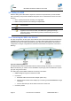
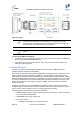

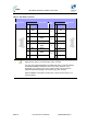
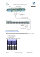
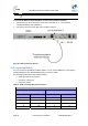

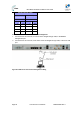

Table Of Contents
- 1 About this Guide
- 2 System Overview
- 3 Installation Prerequisites
- 4 Physical Description
- 5 BSDU Description
- 6 GPSD Description
- 7 GPS Description
- 8 AC/DC Power Converter
- 9 Mounting the Base Station Radio (BSR)
- 10 Mounting the BSDU
- 11 Mounting the GPS
- 12 Mounting the AC/DC Power Converter
- 13 Cabling the BSR
- 14 Connecting the SDA-4S to the power supply
- 15 Connecting Power Cable for SDA-4SDC
- 16 Connecting BSDU to AC/DC Power converter
- 17 Lightning and Surge Protection
- 18 Connecting Third-Party External Antennas
- 19 Appendix

MicroMAX Hardware Installation User Guide
Page 65 Commercial in Confidence UWB-D00068 Rev J
Figure45‐BSR‐to‐BSDUcableconnection
13.4 Connecting BSDU to Network
The BSDU's front panel provides two 10/100/1000 Base-T RJ-45 ports (labeled 1 & 2). These
ports are used for connecting to the service provider's backbone (WAN).
¾ Cable: straight through
¾ Connector: 8-pin RJ-45
¾ Connector pinouts:
Table25‐BSDU‐to‐WANcableconnectorpinouts
Straight-through cable
BSDU WAN
8-pin RJ 45 8-pin RJ 45
Pin Signal Pin Signal
1 Tx+ 1 Rx+
2 Tx- 2 Rx-
3 Rx+ 3 Tx+
6 Rx- 6 Tx-