
User Manual
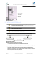
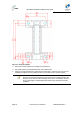
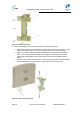
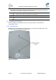
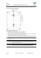
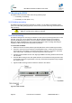
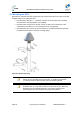
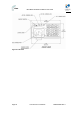
Table Of Contents
- 1 About this Guide
- 2 System Overview
- 3 Installation Prerequisites
- 4 Physical Description
- 5 BSDU Description
- 6 GPSD Description
- 7 GPS Description
- 8 AC/DC Power Converter
- 9 Mounting the Base Station Radio (BSR)
- 10 Mounting the BSDU
- 11 Mounting the GPS
- 12 Mounting the AC/DC Power Converter
- 13 Cabling the BSR
- 14 Connecting the SDA-4S to the power supply
- 15 Connecting Power Cable for SDA-4SDC
- 16 Connecting BSDU to AC/DC Power converter
- 17 Lightning and Surge Protection
- 18 Connecting Third-Party External Antennas
- 19 Appendix

MicroMAX Hardware Installation User Guide
Page 55 Commercial in Confidence UWB-D00068 Rev J
To wall mount the SDA-4S:
On the wall, mark the position of the two mounting hooks. The dimensions of the wall-mounting
hooks are displayed in the template below.
Figure38‐SDA‐4Smountingtemplate
6. Drill holes for each hole that you marked in the step above.
7. Insert wall anchors (supplied) into each of the drilled holes.
8. Insert the 9-inch screws (supplied) into the wall anchors. Ensure at least 2 mm of the screw
is exposed to allow insertion into the SDA-4S mounting holes.
9. Hold the SDA-4S with both hands, and align the entrance to the two mounting hooks with the
screws. Slide the screws into the mounting hooks, by lowering the SDA-4S onto the screws.
Note: For safety, both mounting hooks must be utilized when mounting the
unit.
Note: The SDA-4S is supplied with a 1-metre AC power lead assembly.
Therefore, ensure the unit is mounted within reachable distance to the
customer's mains power outlet.
Note: The maximum cable run between SDA-4S and MicroMAX is 100
meters. Therefore, ensure the unit is mounted within reachable distance.