
User Manual
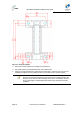
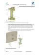
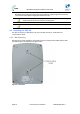
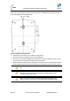
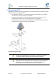
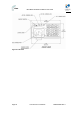
Table Of Contents
- 1 About this Guide
- 2 System Overview
- 3 Installation Prerequisites
- 4 Physical Description
- 5 BSDU Description
- 6 GPSD Description
- 7 GPS Description
- 8 AC/DC Power Converter
- 9 Mounting the Base Station Radio (BSR)
- 10 Mounting the BSDU
- 11 Mounting the GPS
- 12 Mounting the AC/DC Power Converter
- 13 Cabling the BSR
- 14 Connecting the SDA-4S to the power supply
- 15 Connecting Power Cable for SDA-4SDC
- 16 Connecting BSDU to AC/DC Power converter
- 17 Lightning and Surge Protection
- 18 Connecting Third-Party External Antennas
- 19 Appendix

MicroMAX Hardware Installation User Guide
Page 54 Commercial in Confidence UWB-D00068 Rev J
5. Adjust the horizontal positioning of the MicroMAX (see "Web-Based Management" for
MicroMAX antenna alignment using RSS measurements), and then tighten the two M10 x
1.5-hex head screws (20mm length) with the M10 hex nuts.
Note: A third-party thread-locking compound must be applied to the M10-hex
head screws to prevent the bolts from working loose.
Note: For wall mounting, rotation is restricted in the horizontal plane only.
9.3 Installing the SDA-4S
The SDA-4S Type II (or SDA-4SDC Type II) is mounted vertically on a wall within the
communication center.
9.3.1 Wall Mounting
Wall mounting is made possible by the existence of two mounting hooks molded into the SDA-
4S's bottom panel, as displayed in the figure below.
Figure37‐wallmount