
User Manual
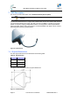
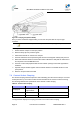
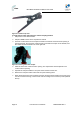
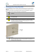
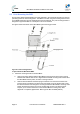
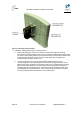
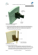
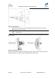
Table Of Contents
- 1 About this Guide
- 2 System Overview
- 3 Installation Prerequisites
- 4 Physical Description
- 5 BSDU Description
- 6 GPSD Description
- 7 GPS Description
- 8 AC/DC Power Converter
- 9 Mounting the Base Station Radio (BSR)
- 10 Mounting the BSDU
- 11 Mounting the GPS
- 12 Mounting the AC/DC Power Converter
- 13 Cabling the BSR
- 14 Connecting the SDA-4S to the power supply
- 15 Connecting Power Cable for SDA-4SDC
- 16 Connecting BSDU to AC/DC Power converter
- 17 Lightning and Surge Protection
- 18 Connecting Third-Party External Antennas
- 19 Appendix

MicroMAX Hardware Installation User Guide
Page 50 Commercial in Confidence UWB-D00068 Rev J
Figure30‐elevationholes
b. Adjust the horizontal position of the MicroMAX by rotating it about the pole, and then
tightening the nuts of the U-bolts.
Note: A thread-locking compound must be used to prevent the bolts from
working loose.
MicroMAX positioning is obtained in two planes by adjustment of the mounting bracket assembly
as shown below.
Figure31–positioning
It is important to provide strain relief and drip loop for Cat-5 cables. Create a drip loop and strain
relief using cable tie, to tie cable to pole, as displayed in the figure below: