
User Manual
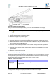
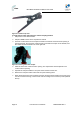
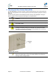
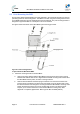
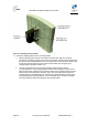
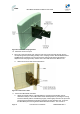
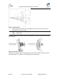
Table Of Contents
- 1 About this Guide
- 2 System Overview
- 3 Installation Prerequisites
- 4 Physical Description
- 5 BSDU Description
- 6 GPSD Description
- 7 GPS Description
- 8 AC/DC Power Converter
- 9 Mounting the Base Station Radio (BSR)
- 10 Mounting the BSDU
- 11 Mounting the GPS
- 12 Mounting the AC/DC Power Converter
- 13 Cabling the BSR
- 14 Connecting the SDA-4S to the power supply
- 15 Connecting Power Cable for SDA-4SDC
- 16 Connecting BSDU to AC/DC Power converter
- 17 Lightning and Surge Protection
- 18 Connecting Third-Party External Antennas
- 19 Appendix

MicroMAX Hardware Installation User Guide
Page 48 Commercial in Confidence UWB-D00068 Rev J
Figure27‐Mountingbracketattached
9. Attach the clamping bracket to the mounting bracket:
a. Slide an M6-spring lock washer onto an M6-hex head screw. Align the mounting
bracket's and clamping bracket's pivot holes, such that the clamping bracket is aligned to
the inside of the mounting bracket. From the external side of the mounting bracket, insert
the M6-hex head screw into the pivot holes and then fasten, but not tightly. (The
clamping bracket provides a built-in nut.)
b. Choose an elevation hole on the mounting bracket and then align it with the
corresponding hole on the clamping bracket. Slide an M6-spring lock washer onto an
M6-hex head screw, and then from the external side of the mounting bracket, insert the
M6-hex head screw through the elevation hole on the mounting bracket and into the
clamping bracket's corresponding hole. Fasten but not tightly the M6-hex head screw
(the clamping bracket provides built-in nut). The elevation hole can later be changed
according to desired antenna orientation in the elevation plane.