
User Manual
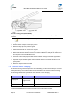
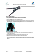
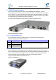
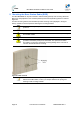
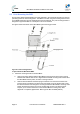
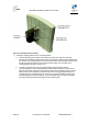
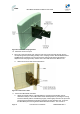
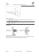
Table Of Contents
- 1 About this Guide
- 2 System Overview
- 3 Installation Prerequisites
- 4 Physical Description
- 5 BSDU Description
- 6 GPSD Description
- 7 GPS Description
- 8 AC/DC Power Converter
- 9 Mounting the Base Station Radio (BSR)
- 10 Mounting the BSDU
- 11 Mounting the GPS
- 12 Mounting the AC/DC Power Converter
- 13 Cabling the BSR
- 14 Connecting the SDA-4S to the power supply
- 15 Connecting Power Cable for SDA-4SDC
- 16 Connecting BSDU to AC/DC Power converter
- 17 Lightning and Surge Protection
- 18 Connecting Third-Party External Antennas
- 19 Appendix

MicroMAX Hardware Installation User Guide
Page 44 Commercial in Confidence UWB-D00068 Rev J
Figure21‐Contactcrimptool
To crimp CAT-5e cable using discrete contact crimping method:
1. Strip 50 mm of the cable's sheath.
2. Strip 3 to 4 mm of each wire to expose their strands.
3. Insert the contact socket on the crimper's left side such that the contact socket's opening is
pointing upwards, the end of the contact socket is flush with the crimper on the left side, and
the contact socket end stands out on the right side.
Figure22‐Insertingsocketintocrimper
4. Place the wire in the contact socket’s opening. The exposed wire must be placed in the
contact socket’s opening.
5. Squeeze the crimper handles to crimp the contact socket over the wire.
6. Remove the crimped contact socket and crimp the remaining wires.
7. When all the wires have been crimped, insert the crimped contact sockets into the rear of the
Circular connector housing, in their correct order according to the connector pinouts (defined
above).