
User Manual
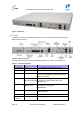

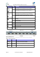
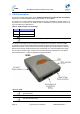
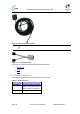
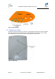
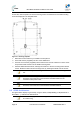
Table Of Contents
- 1 About this Guide
- 2 System Overview
- 3 Installation Prerequisites
- 4 Physical Description
- 5 BSDU Description
- 6 GPSD Description
- 7 GPS Description
- 8 AC/DC Power Converter
- 9 Mounting the Base Station Radio (BSR)
- 10 Mounting the BSDU
- 11 Mounting the GPS
- 12 Mounting the AC/DC Power Converter
- 13 Cabling the BSR
- 14 Connecting the SDA-4S to the power supply
- 15 Connecting Power Cable for SDA-4SDC
- 16 Connecting BSDU to AC/DC Power converter
- 17 Lightning and Surge Protection
- 18 Connecting Third-Party External Antennas
- 19 Appendix

MicroMAX Hardware Installation User Guide
Page 37 Commercial in Confidence UWB-D00068 Rev J
6.2 Ports
The GPSD adapter provides ports on the front panel, which are described in the table below:
Table18‐GPSDports
Port Interface
4 x 8-pin RJ-
45
10/100BaseT with subscriber's BSRs (up to 4).
15-pin D-type
(female)
For connection to external GPS antenna for SYNC from the GPS and power
to the GPS.
4 x “Y” cables Split – supplies power & data from SDA-4S(DC) and SYNC from GPSD.
Note: Cables are clearly labeled “MicroMAX” and
“GPSD”. The RJ45 Jacks are clearly labeled
“MicroMAX” and “GPSD”.
AC power
socket
Subscriber's power outlet (110-240 VAC, 1A, 50/60 Hz, 50W)
OR
DC power
socket
DC power outlet (10-52 VDC, 24W)
6.3 LEDs
The GPSD provides LED indicators on the top panel, which are described in the table below:
Table19‐GPSDLEDdescription
LED Color Status Description
Orange
On When the board is in reset (normally will blink for 200ms
when power ON - Power on reset).
Green
Blinking When receiving 1PPS from the GPS blinks 1 second for
300-400 ms
SYNC
Off No PPS was received from the GPS
On Appropriate power is being fed to the unit
Power Green
Off No power
The figure below displays the LEDs which are located on the top panel of the GPSD: