
User Manual
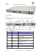

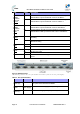
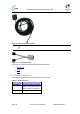
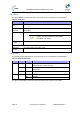
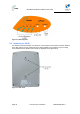
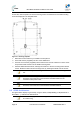
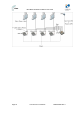
Table Of Contents
- 1 About this Guide
- 2 System Overview
- 3 Installation Prerequisites
- 4 Physical Description
- 5 BSDU Description
- 6 GPSD Description
- 7 GPS Description
- 8 AC/DC Power Converter
- 9 Mounting the Base Station Radio (BSR)
- 10 Mounting the BSDU
- 11 Mounting the GPS
- 12 Mounting the AC/DC Power Converter
- 13 Cabling the BSR
- 14 Connecting the SDA-4S to the power supply
- 15 Connecting Power Cable for SDA-4SDC
- 16 Connecting BSDU to AC/DC Power converter
- 17 Lightning and Surge Protection
- 18 Connecting Third-Party External Antennas
- 19 Appendix

MicroMAX Hardware Installation User Guide
Page 32 Commercial in Confidence UWB-D00068 Rev J
Figure7‐BSDUfront
5.2 Ports
The BSDU provides various hardware interfaces on its front and rear panel as described in the
tables and figures below.
Figure8‐BSDUFrontPanel
The following table lists the front panel hardware interfaces (refer to the front panel figure):
Table13‐FrontPanelInterfaces
Port Label Interface
8-pin RJ-45 (4) 10/100 4 x 10/100 BaseT general purpose switch
8-pin RJ-45 MNG 10/100 BaseT for out-of-band management
8-pin RJ-45 (2) 10/100/1000 1 / 2 1 - Interface with provider’s backbone
2 – Daisy-chained BSDUs, interface with another
BSDU for cascading
SMA (2) GPS
10MHz IN & 1PPS IN
Interface with GPS for global clock synchronization
by means of 2 signals: 10 MHz and 1 PPS
For future use
SMA (2) CASCADE
10MHz & 1PPS
Interfaces with a daisy-chained BSDU for
cascading the 2 GPS signals
For future use
8-pin RJ-45 GPS COM Interfaces with the GPS serial port for getting
status and alarms
8-pin RJ-45 CONSOLE BSDU serial port for initial configuration
Power
Receptacle
-48VDC -48 VDC supply from external feeding source