
User Manual
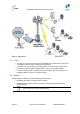
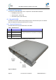
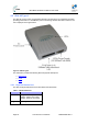
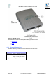
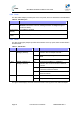
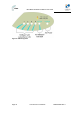
Table Of Contents
- 1 About this Guide
- 2 System Overview
- 3 Installation Prerequisites
- 4 Physical Description
- 5 BSDU Description
- 6 GPSD Description
- 7 GPS Description
- 8 AC/DC Power Converter
- 9 Mounting the Base Station Radio (BSR)
- 10 Mounting the BSDU
- 11 Mounting the GPS
- 12 Mounting the AC/DC Power Converter
- 13 Cabling the BSR
- 14 Connecting the SDA-4S to the power supply
- 15 Connecting Power Cable for SDA-4SDC
- 16 Connecting BSDU to AC/DC Power converter
- 17 Lightning and Surge Protection
- 18 Connecting Third-Party External Antennas
- 19 Appendix

MicroMAX Hardware Installation User Guide
Page 29 Commercial in Confidence UWB-D00068 Rev J
4.3.2 Ports
The SDA-4SDC adapter provides ports on the front panel, which are described in the table below:
Table10‐SDA‐4SDCports
Port Interface
4 x 8-pin RJ-
45
10/100BaseT with subscriber's network (supports Auto Negotiation and
MDI/MDI-X automatic crossover, allowing connection of straight-through or
crossover cables)
15-pin D-type
(female)
10/100BaseT with BSR
DC power
socket
DC power outlet (10-52 VDC, 24W)
4.3.3 LEDs
The SDA-4S (all types) adapter provides LED indicators on the top panel, which are described in
the table below:
Table11‐SDA‐4SLEDs
LED Color Status Description
On Physical link (10BaseT or 100BaseT)
between SDA-4S adapter and BSR
Blinking Traffic currently flowing between SDA-4S and
BSR
UPLINK
Yellow (100BaseT) or
Orange (10BaseT)
Off No link between SDA-4S and BSR
On Physical link (10BaseT or 100BaseT)
between SDA-4S and subscriber's Ethernet
network
Blinking Traffic currently flowing between SDA-4S and
subscriber's Ethernet network
1, 2, 3,
4
Yellow (100BaseT) or
Orange (10BaseT)
Off No link between SDA-4S and subscriber's
Ethernet network
On Power received by SDA-4S
POWER Green
Off No power received by SDA-4S
The figure below displays the LEDs which are located on the top panel of the SDA-4S adapter: