
User Manual
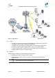
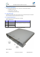
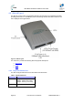
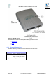
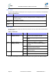
Table Of Contents
- 1 About this Guide
- 2 System Overview
- 3 Installation Prerequisites
- 4 Physical Description
- 5 BSDU Description
- 6 GPSD Description
- 7 GPS Description
- 8 AC/DC Power Converter
- 9 Mounting the Base Station Radio (BSR)
- 10 Mounting the BSDU
- 11 Mounting the GPS
- 12 Mounting the AC/DC Power Converter
- 13 Cabling the BSR
- 14 Connecting the SDA-4S to the power supply
- 15 Connecting Power Cable for SDA-4SDC
- 16 Connecting BSDU to AC/DC Power converter
- 17 Lightning and Surge Protection
- 18 Connecting Third-Party External Antennas
- 19 Appendix

MicroMAX Hardware Installation User Guide
Page 25 Commercial in Confidence UWB-D00068 Rev J
Note: BSR models that use third-party external antennas provide an N-type
receptacle for attaching an external antenna.
4.1.2 Ports
The table below defines the different ports on the bottom panel.
Table6‐BSRports
Port interfaces Description
DB 15 IDU/ODU interface:
¾ Fast Ethernet from/to SDA-4S or SDA-4SDC
Type II and BSDU
¾ Power from SDA-4S Type II or SDA-4SDC
Type II and BSDU
¾ TDD Tx/Rx sync from BSDU
DB 9 Engineering applicability (Technical Service only)
N Type RF connector - relevant
when implementing external antenna
External antenna connection
Note: Some previous models (still in use) have an RJ45 port with cover
which has been discontinued as of December 2006.
MicroMAX is powered from the indoor integrated LAN switch:
Note: The SDA-4S Type II and the SDA-4SDC are physically (externally) the
same other than the power socket.