
User's Manual
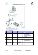
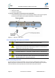
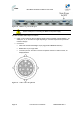
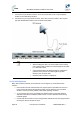
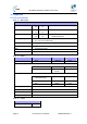
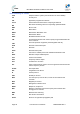
Table Of Contents
- 1.1 Purpose
- 1.4 Referenced Documentation
- 2.1 MicroMAX Frequency Ranges
- 2.2 System Components
- 2.3 Customer Benefits
- 2.4 Architecture
- 2.5 Power
- 2.6 Models
- 3.1 Package Contents
- 3.2 Required Tools
- 3.3 Radio Site Planning
- 4.1 MicroMAX BSR
- 4.2 SDA-4S Type II
- 4.3 SDA-4SDC Type II
- 5.1 Physical Dimensions
- 5.2 Ports
- 6.1 Physical Dimensions
- 6.2 Ports
- 6.3 LEDs
- 6.4 Mounting the GPSD
- 6.5 GPSD Architecture
- 7.1 Physical Dimensions
- 7.2 Ports
- 7.3 Crimping GPS Cable
- 7.4 Contact Socket Crimping
- 8.2 Redundant PS Unit
- 9.1 Pole-Mounting the BSR
- 9.2 Wall-Mounting the BSR (Optional)
- 9.3 Installing the SDA-4S
- 10.1 Desktop mounting
- 10.2 Rack mounting
- 12.1 Rack Mounting
- 12.2 Connecting Redundant PS Unit
- 13.1 Connecting the BSR to the SDA-4S
- 13.2 SDA-4S Type II
- 13.3 Connecting the BSR to BSDU
- 13.4 Connecting BSDU to Network
- 13.5 Connecting BSDUs
- 13.6 Connecting BSDU for SNMP Management
- 14.1 Connecting the SDA-4S Type II
- 14.2 Connecting the SDA-4SDC Type II
- 14.3 Connecting SDA-4S to Ethernet Network
- 15.1 Housing the Connectors
- 15.2 Connecting to the SDA-4SDC
- 16.1 Connections
- 16.2 Power Cable Assembly
- 16.3 Housing the Connectors
- 16.4 Cable Connection
- 17.1 Lightning Protection
- 17.2 Cable Preparation (for grounding)
- 17.3 FM Interference & ESD Protection Recommendations
- 17.4 Connecting Lightning and Surge Protector
- 17.5 Lightning and Surge Protection Connection Scenarios
- 18.1 Connecting GPS Antenna to BSDU
- 19.1 Environmental
- 19.2 Glossary of Terms
- 19.3 Revision History
- 19.4 Contact Information

MicroMAX Hardware Installation User Guide
Page 93 Commercial in Confidence UWB-D00068 Rev J
The following lists the cable setup for attaching the external antenna:
¾ Cable: RF coaxial
¾ Connector: N-type male
To connect a third-party external antenna to the MicroMAX:
¾ Connect the N-type male connector of the third-party antenna to the N-type receptacle
located on the MicroMAX's panel (labeled ANTENNA), as displayed below.
Figure 87 - Antenna connection
18.1 Connecting GPS Antenna to BSDU
Caution: To avoid electrical or fire hazard, ensure that the connection to the
GPS is made prior to connecting the BSDU to the power supply.
Caution: A primary lightning protection device must be provided by the
operator/customer as part of an extra-building installation to ensure transient
voltage levels of less than 600 V maximum.
Caution: Changes or modifications to this equipment not expressly approved
by Airspan Networks Inc. could result in violation of Part 15 of the FCC rules.
Caution: This is a Class B product. In a domestic environment this product
may cause radio interference in which case the user may be required to take
adequate measures to correct the interference.
18.1.1 Connecting the GPS
The GPS antenna connects to the BSDU's 15-pin D-type port, labeled GPS, located on the
BSDU's rear panel, as shown below. The connection to the GPS is made through a 12-pin RS-
422 serial interface port that provides both communication and power interfaces.